Image encoding apparatus and an image decoding apparatus

a technology of image coding and decoding apparatus, which is applied in the field of image coding apparatus and image decoding apparatus, can solve the problems of deteriorating coding efficiency, difficult to maintain consistency with another coding system, and relatively increasing the percentage of block mode data in the created coded signal, so as to prevent the coding efficiency from drastically deteriorating

Inactive Publication Date: 2002-02-05
GK BRIDGE 1
View PDF24 Cites 42 Cited by
  • Summary
  • Abstract
  • Description
  • Claims
  • Application Information

AI Technical Summary

Benefits of technology

The objective of the present invention is to provide an image coding apparatus and image decoding apparatus that will prevent the coding efficiency from drastically deteriorating even for those images that contain numerous blocks without movement information, quadrature conversion coefficient or significant form, etc. within one frame.
In the first and second embodiments above, the mode data of three peripheral blocks was used to predict the mode data of the block to be coded, but it is also possible to increase the number of reference blocks.

Problems solved by technology

However, since the MMR system is a system in which processing is performed for the entire one frame input, it is difficult to maintain consistency with another coding system adopted in ITU-T H.261 and ISO / IEC MPEG, etc. in which one frame is divided into a plurality of blocks and processing is performed in block units.
However, the coding method that performs coding by dividing the above image block into the coding mode data that indicates the coding mode of said block and the data concerning the pixel values within said block has the problem that the percentage of the block mode data in the created coded signal relatively increases, deteriorating its coding efficiency in the case that blocks without movement information, quadrature conversion coefficient or significant form, etc. increases within one frame.

Method used


Image

  • Image encoding apparatus and an image decoding apparatus
  • Image encoding apparatus and an image decoding apparatus
  • Image encoding apparatus and an image decoding apparatus

Examples


first embodiment

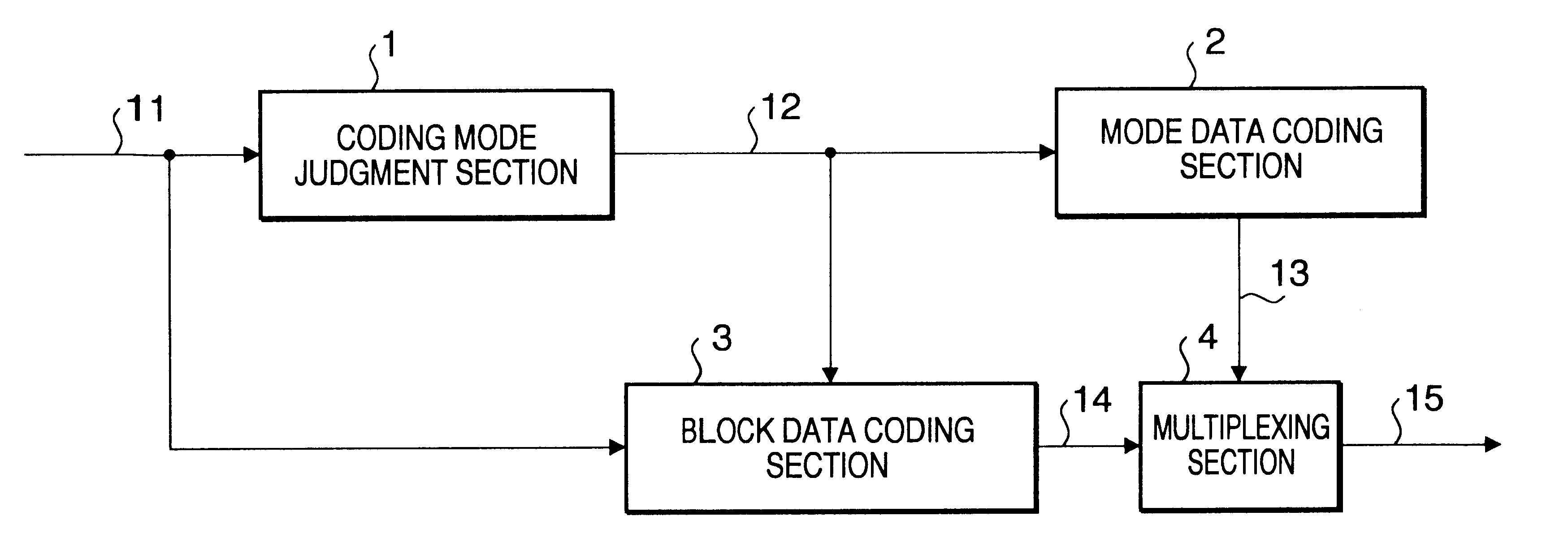
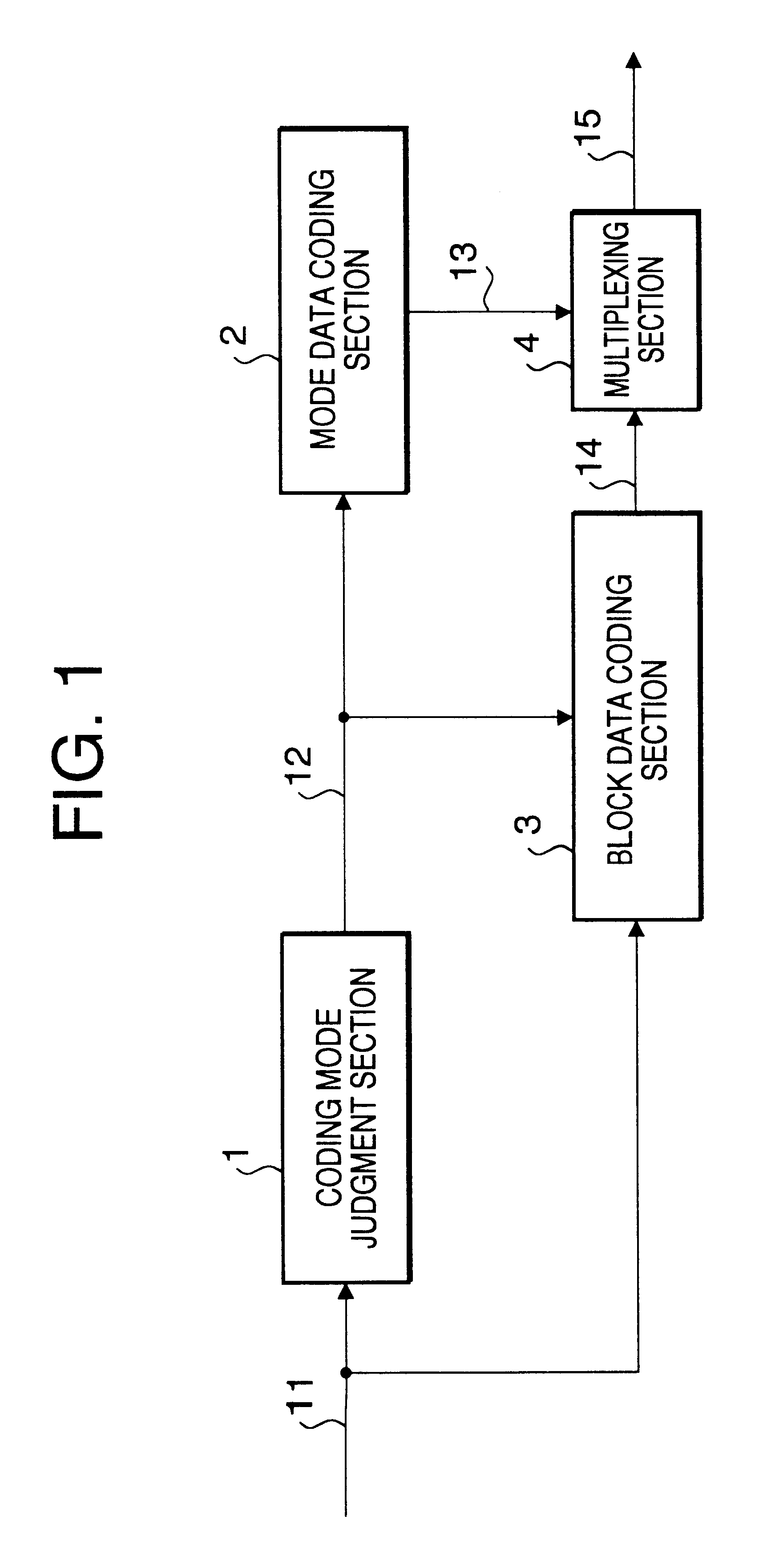
On the other hand, the pixel data of the pixel block is coded by block data coding section 3 as in the case of the first embodiment, and the code word regarding the block data is stored in memory 103 and organized into code word 113 regarding the block data corresponding to the entire one frame.

Then, multiplexing section 104 multiplexes code word 112 regarding the mode data and code word 113 regarding the block data of the entire one frame and outputs coded image signal 114.

third embodiment

Thus, the third embodiment stores the mode data of one-frame pixel block in memory before coding a plurality of mode data items collectively. In the code word table to encode a plurality of mode data items collectively, shorter code words are set for combinations of the same mode data.

fourth embodiment

(Fourth embodiment)

FIG. 14 is a block diagram of the image decoding system that relates to a fourth embodiment of the present invention. In said figure, the same signals as those shown in FIG. 1 and FIG. 8 are assigned the same numbers and their explanations are omitted.

The image decoding system of the present embodiment comprises de-multiplexing section 141 that separates a code word string regarding the mode data and a code word string regarding the block data from a coded signal, mode data decoding section 142 that obtains mode data from a code word string regarding the mode data, memory 143 that stores mode data of all blocks corresponding to one frame, and block data decoding section 83 that reproduces pixel values from a code word string regarding the block data.

Mode data decoding section 142 has a code word table shown in FIG. 11 to decode the code word of the mode data coded by the image coding system in the third embodiment. Mode data decoding section 142 decodes the code w...


PUM


Abstract

The mode data of a block to be coded is predicted from the mode data of peripheral blocks already coded, and coded using a code word table switched according to a hitting ratio of prediction. In the code word table, the code word length is set shorter for coding modes with high hitting ratio.

Description

The present invention relates to an image coding apparatus and an image decoding apparatus for coding and decoding digital images, and also relates to recording media in which image coding / decoding programs are stored.One of known conventional image coding systems requiring reversibility is the MMR (Modified Modified Read) system which is used in facsimile applications. However, since the MMR system is a system in which processing is performed for the entire one frame input, it is difficult to maintain consistency with another coding system adopted in ITU-T H.261 and ISO / IEC MPEG, etc. in which one frame is divided into a plurality of blocks and processing is performed in block units. Thus, the MMMR (Modified MMR) that is an improved version of the MMR system is adopted as an verification model of MPEG4 (ISO / IECJTC / SC29 / WG11 N1277, July 1996).An image coding system which divides a one-frame image into two-dimensional blocks consisting of a plurality of pixels and codes the image for...

Claims


Application Information

Patent Timeline
Patent Type & Authority Patents(United States)
IPC IPC(8): G06T9/00H04N7/34H04N7/26H04N7/30H04N19/593
CPCH04N19/176H04N19/46H04N19/196H04N19/157H04N19/593H04N19/463H04N19/13H04N19/91H04N19/60H04N7/24
Inventor MATSUMOTO, TAISUKE
Owner GK BRIDGE 1
Why Eureka
Try Eureka