Forming method of metal interconnection structure

A metal interconnection structure and interconnection structure technology, applied in electrical components, semiconductor/solid-state device manufacturing, circuits, etc., can solve problems affecting the service life of electrical testing equipment and affecting product yields, etc.

Pending Publication Date: 2021-01-08
NEXCHIP SEMICON CO LTD
View PDF0 Cites 2 Cited by
  • Summary
  • Abstract
  • Description
  • Claims
  • Application Information

AI Technical Summary

Problems solved by technology

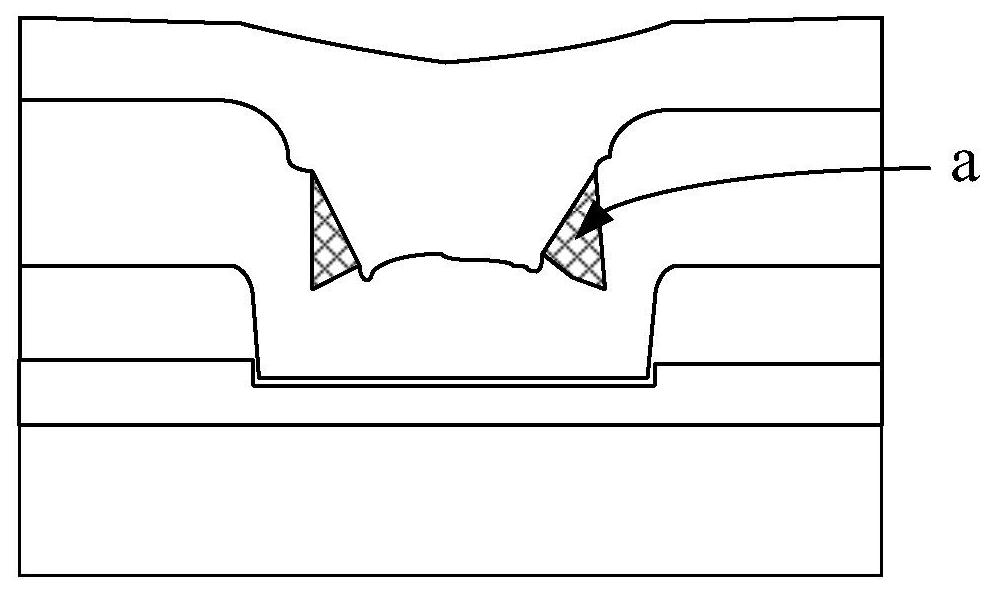
[0003] like figure 1 As shown, in the prior art, when forming the top metal interconnection layer, it is easy to appear a protective layer residue a above the top via (Top V

Method used


Image

  • Forming method of metal interconnection structure
  • Forming method of metal interconnection structure
  • Forming method of metal interconnection structure

Examples


Embodiment Construction

[0037] A method for forming a metal interconnection structure of the present invention will be further described in detail below. The invention will now be described in more detail with reference to the accompanying drawings, in which preferred embodiments of the invention are shown, it being understood that those skilled in the art may modify the invention described herein and still achieve the advantageous effects of the invention. Therefore, the following description should be understood as the broad knowledge of those skilled in the art, but not as a limitation of the present invention.

[0038] In the interest of clarity, not all features of an actual implementation are described. In the following description, well-known functions and constructions are not described in detail since they would obscure the invention with unnecessary detail. It should be appreciated that in the development of any actual embodiment, numerous implementation details must be worked out to achie...


PUM


Abstract

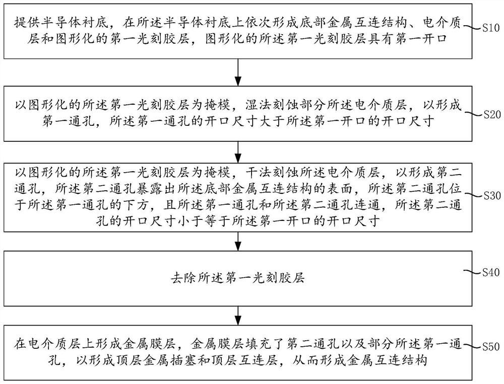
The invention provides a forming method of a metal interconnection structure. A first through hole is formed through wet etching firstly, then a second through hole is formed through dry etching, thefirst through hole is communicated with the second through hole, the first through hole is located above the second through hole, and due to the fact that the opening size of the first through hole islarger than that of the second through hole, The overall depth and width of the first through hole and the second through hole after communication are reduced, and when a metal film layer and a protective layer are formed subsequently, protective layer residues do not appear on the surface of a top metal plug, so that influence of the protective layer residues on the product yield during subsequent packaging is avoided, and influence of the service life of the electrical test equipment (probe) during the WAT test is also avoided.

Description

technical field [0001] The invention relates to the field of semiconductor manufacturing technology, in particular to a method for forming a metal interconnection structure. Background technique [0002] In the semiconductor back-end process, a multi-layer metal interconnection structure can be provided on the semiconductor substrate according to different needs. Each layer of metal interconnection layer includes a metal interconnection line and an insulating layer, and trenches and via holes are formed in the insulating layer. Then metal is deposited in the groove and the through hole, and the deposited metal is the metal interconnection line, and generally copper or aluminum is selected as the material of the metal interconnection line. [0003] Such as figure 1 As shown, in the prior art, when forming the top metal interconnection layer, it is easy to appear the residue a of the protective layer above the top via (Top Via), which not only affects the yield of the product...

Claims


Application Information

Patent Timeline
IPC IPC(8): H01L21/768
CPCH01L21/76883H01L21/76877H01L21/76895
Inventor 张国伟许宗能王建智
Owner NEXCHIP SEMICON CO LTD
Why Eureka
Try Eureka