
Dimming control circuit and control method thereof

A dimming control circuit and dimming technology, applied in electrical components and other directions, can solve the problems of high cost and complicated circuits, and achieve the effect of stabilizing the power supply current

Active Publication Date: 2021-01-08
HANGZHOU SILAN MICROELECTRONICS
View PDF6 Cites 2 Cited by
  • Summary
  • Abstract
  • Description
  • Claims
  • Application Information

AI Technical Summary

Problems solved by technology

The existing dimming control circuit is complex and expensive

Method used


Image

  • Dimming control circuit and control method thereof
  • Dimming control circuit and control method thereof
  • Dimming control circuit and control method thereof

Examples


Embodiment Construction

[0062] Various embodiments of the invention will be described in more detail below with reference to the accompanying drawings. In the various drawings, the same elements are denoted by the same or similar reference numerals. For the sake of clarity, various parts in the drawings have not been drawn to scale.

[0063] The specific implementation manners of the present invention will be further described in detail below in conjunction with the accompanying drawings and embodiments.

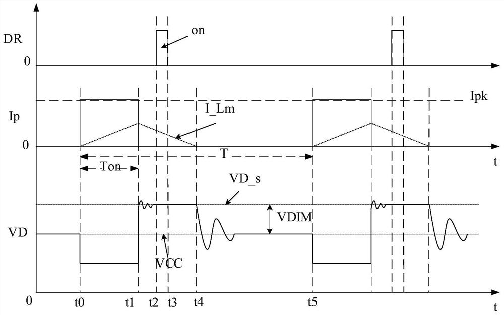
[0064] figure 1 A schematic circuit diagram of a dimming control circuit provided according to an embodiment of the present invention is shown. The dimming control circuit 100 generates an excitation signal to supply power to the dimmer 200 and converts the 0-10V dimming signal generated by the dimmer 200 into a dimming reference signal VDIM representing the dimming signal.

[0065] Such as figure 1 As shown, the dimming control circuit 100 includes an excitation conversion circuit 110 , an iso...


PUM


Abstract

The invention discloses a dimming control circuit and a control method thereof, and the dimming control circuit comprises: an excitation conversion circuit which generates an excitation signal; an isolation circuit which comprises a primary side winding and a secondary side winding, wherein the primary side winding of the isolation circuit is connected with the excitation conversion circuit, receives the excitation signal and transmits the excitation signal to the secondary side winding of the isolation circuit; and a rectifying circuit, wherein the input end of the rectifying circuit is connected with the secondary winding of the isolating circuit, the output end of the rectifying circuit is connected with the dimmer, and the excitation conversion circuit comprises an excitation module, the excitation module comprises a power supply voltage and a first current source, a first end of a primary winding of the isolation circuit receives the power supply voltage, and the first current source is connected between a second end of the primary winding of the isolation circuit and a first grounding end to generate an excitation signal. The constant current source is adopted to generate theexcitation signal, power can be stably supplied to the dimmer, and the circuit is simple in structure and low in cost.

Description

technical field [0001] The present invention relates to power electronics technology, and more specifically, to a dimming control circuit and a control method thereof. Background technique [0002] In the traditional 0-10V isolated dimming control circuit, the external 0-10V voltage signal is usually converted into a corresponding PWM signal through a triangular wave generator, PWM (pulse width modulation) adjustment and other complex analog circuits, or the external The 0-10V voltage signal is converted into a corresponding control signal, and then transmitted to the dimming pin of the primary main control chip through an isolated photocoupler to adjust the current input to the LED. After the external 0-10V voltage signal is converted into a control signal by single-chip microcomputer technology or conventional analog PWM adjustment, the control signal is transmitted to the primary main control chip through an isolated photocoupler. The entire circuit is complex and costly....

Claims


Application Information

Patent Timeline
Patent Type & Authority Applications(China)
IPC IPC(8): H05B45/345H05B45/382H05B45/385
CPCH05B45/345H05B45/382H05B45/385
Inventor 叶美盼
Owner HANGZHOU SILAN MICROELECTRONICS
Learn More