Metal raw material cutting machining device for high-end equipment manufacturing

A cutting and raw material technology, used in metal processing equipment, metal processing machinery parts, manufacturing tools, etc., can solve problems such as insufficient shape, increased worker workload, low cutting efficiency, etc., to prevent self-movement and improve cutting processing. Efficiency, the effect of reducing the workload of workers

Active Publication Date: 2021-01-12
山东辰之翼信息科技有限公司
View PDF6 Cites 15 Cited by
  • Summary
  • Abstract
  • Description
  • Claims
  • Application Information

AI Technical Summary

Problems solved by technology

[0002] Metal materials are usually used in the manufacture of high-end equipment, and plate-shaped metal raw materials need to be cut into circular shapes. At present, cutting and processing plate-shaped metal raw materials into circular shapes is generally done manually. When cutting and processing manually , the hand-held electric cutting machine makes a circular motion along the plate-shaped metal raw material, so as to realize the cutting and processing of the plate-shaped metal raw material into a circle, but there will be errors in cutting the circle with the manual hand-held electric cutting machine, resulting in a shape that is not standard enough, which will cause Affect the next processing work. In order to reduce errors, workers will use a pen to draw a circle on the plate-shaped metal raw material, and then use a cutting machine to cut along the circle, but this method increases the workload of the workers and the cutting efficiency is low.

Method used


Image

  • Metal raw material cutting machining device for high-end equipment manufacturing
  • Metal raw material cutting machining device for high-end equipment manufacturing
  • Metal raw material cutting machining device for high-end equipment manufacturing

Examples


Embodiment Construction

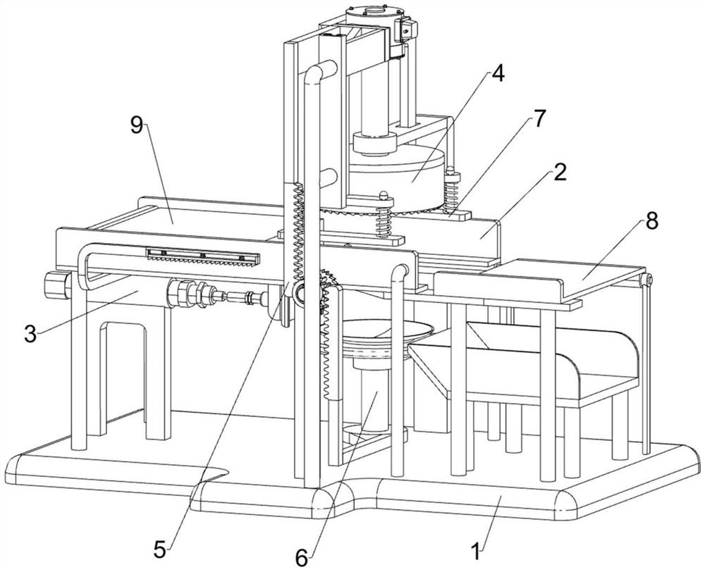
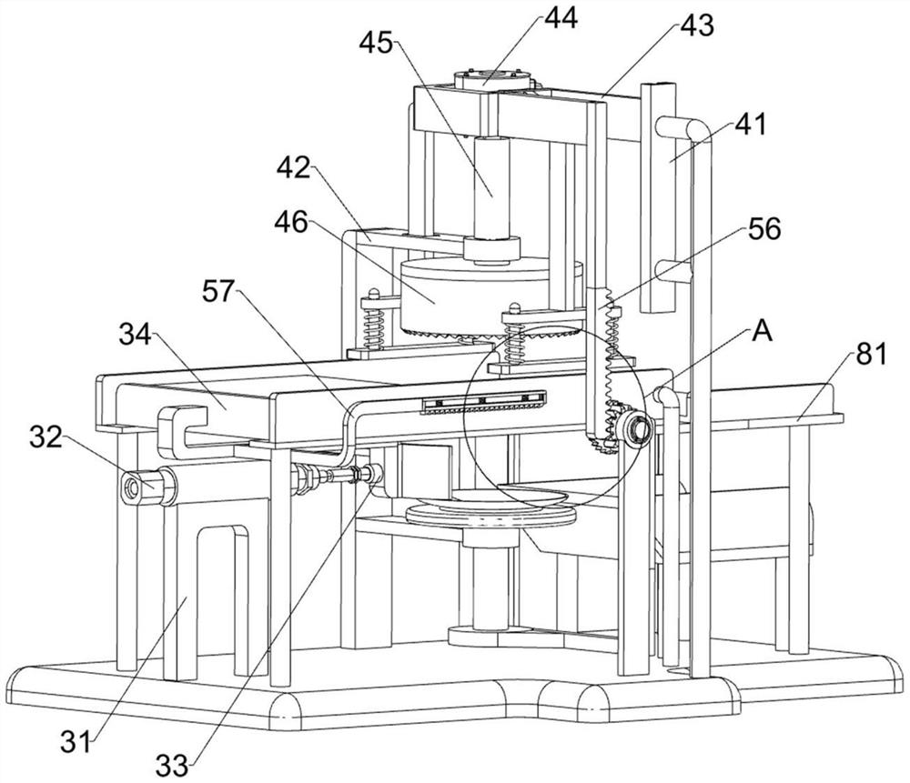
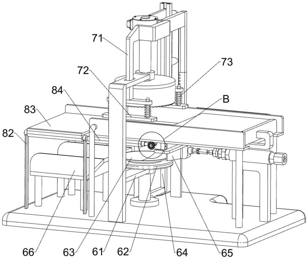
[0024] according to Figure 1-4 , the present invention includes a base plate 1, a guide pallet frame 2, a propulsion mechanism 3, a cutting mechanism 4, a linkage mechanism 5 and a bottom support mechanism 6, the front and rear sides of the top of the base plate 1 are connected with the guide pallet frame 2, and the base plate 1 A propulsion mechanism 3 is installed, a cutting mechanism 4 is installed on the base plate 1, a linkage mechanism 5 is installed between the base plate 1, the propulsion mechanism 3 and the cutting mechanism 4, a bottom support mechanism 6 is installed on the cutting mechanism 4, and the bottom support mechanism 6 and the linkage Mechanism 5 transmission connection.

[0025] The propulsion mechanism 3 includes a first fixed mount 31, a cylinder 32, a first connecting frame 33 and a push plate 34. The left side of the top of the bottom plate 1 is connected with a first fixed mount 31, and a cylinder 32 is installed on the first fixed mount 31. The cyl...


PUM


Abstract

The invention discloses a metal raw material cutting machining device for high-end equipment manufacturing. The metal raw material cutting machining device comprises a bottom plate, guide supporting plate frames, a propelling mechanism, a cutting mechanism, a linkage mechanism and a bottom supporting mechanism, wherein the two sides of the bottom plate are connected with the guide supporting plateframes; the propelling mechanism is arranged on the bottom plate; the cutting mechanism is arranged on the bottom plate; the linkage mechanism is arranged among the bottom plate, the propelling mechanism and the cutting mechanism; and the bottom supporting mechanism is arranged on the cutting mechanism and is in transmission connection with the linkage mechanism. According to the metal raw material cutting machining device, the propelling mechanism can push plate-shaped metal raw materials to the position of the cutting mechanism, the linkage mechanism can drive the cutting mechanism and thebottom supporting mechanism to work at the same time, the cutting mechanism can cut the plate-shaped metal raw materials into circles, and the cut circular metal raw materials and waste can be separated through the bottom supporting mechanism.

Description

technical field [0001] The invention relates to a cutting and processing device, in particular discloses a metal raw material cutting and processing device for high-end equipment manufacturing. Background technique [0002] Metal materials are usually used in the manufacture of high-end equipment, and plate-shaped metal raw materials need to be cut into circular shapes. At present, cutting and processing plate-shaped metal raw materials into circular shapes is generally done manually. When cutting and processing manually , the hand-held electric cutting machine makes a circular motion along the plate-shaped metal raw material, so as to realize the cutting and processing of the plate-shaped metal raw material into a circle, but there will be errors in cutting the circle with the manual hand-held electric cutting machine, resulting in a shape that is not standard enough, which will cause Affect the next processing work. In order to reduce errors, workers will draw a circle on ...

Claims


Application Information

Patent Timeline
Patent Type & Authority Applications(China)
IPC IPC(8): B23D79/00B23Q3/00B23Q11/00
CPCB23D79/00B23Q3/00B23Q11/0042
Inventor 李春霞
Owner 山东辰之翼信息科技有限公司
Why Eureka
Try Eureka