Supercharge Your Innovation With Domain-Expert AI Agents!

Clamping device for laser cutting machine

A laser cutting machine and clamping device technology, applied in auxiliary devices, laser welding equipment, welding/cutting auxiliary equipment, etc., can solve the problems of base plate damage, lack of adjustment, troublesome fixing, etc., and achieve simple design and structure of the device. Easy cutting operation, easy fixing effect

Inactive Publication Date: 2021-01-12
杭州鹏遒供应链管理有限公司
View PDF8 Cites 0 Cited by
  • Summary
  • Abstract
  • Description
  • Claims
  • Application Information

AI Technical Summary

Problems solved by technology

[0004] The object of the present invention is to provide a clamping device for a laser cutting machine to solve the problem that the traditional laser cutting proposed in the background technology uses a single clamp for clamping when the material is fixed and clamped. It is very troublesome to fix one by one, and at the same time, the material cannot be overhead, which will cause damage to the bottom plate supported by the bottom surface during laser cutting, which will cause certain losses in other aspects, which is not conducive to the current laser cutting work. Fixing at the same time The rear end is not adjustable, so that it is necessary to remove the clips one by one when it needs to be adjusted, which causes a certain amount of trouble and time-consuming and labor-intensive work, which greatly affects the working efficiency of laser cutting.

Method used


Image

  • Clamping device for laser cutting machine
  • Clamping device for laser cutting machine
  • Clamping device for laser cutting machine

Examples


Embodiment Construction

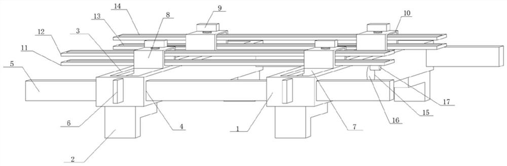
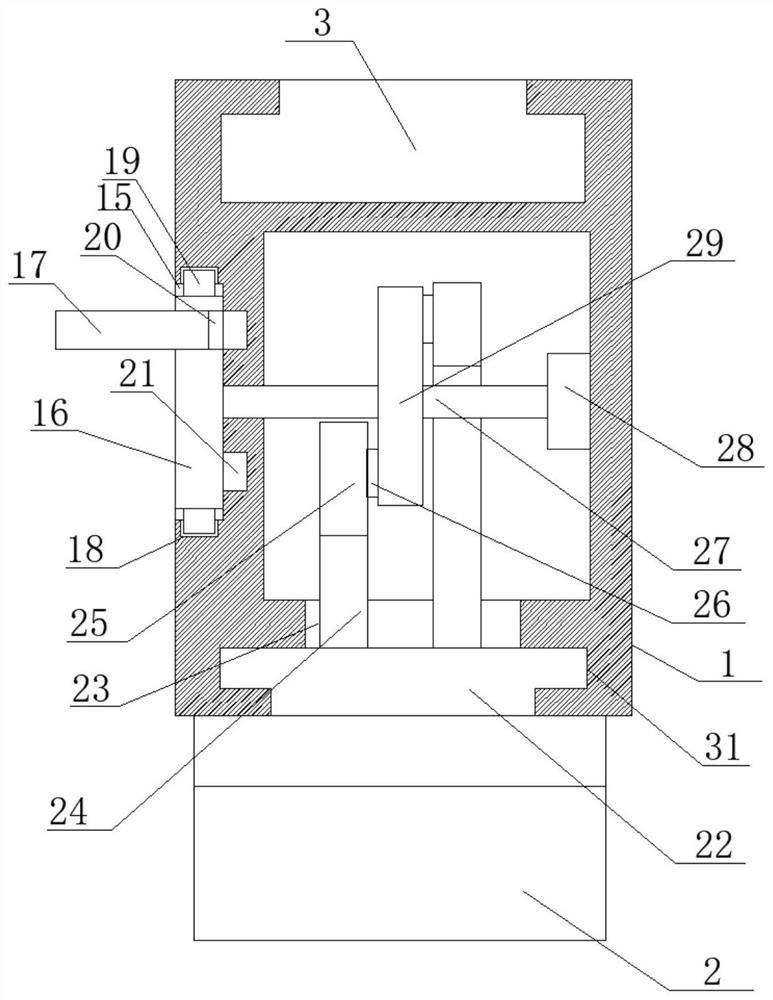
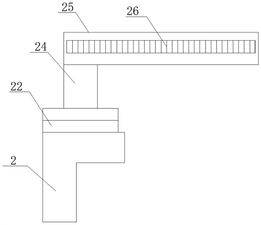
[0026] see Figure 1-3 , in an embodiment of the present invention, a clamping device for a laser cutting machine includes a fixed cross bar 1, the bottom surface of the fixed cross bar 1 is connected with an extrusion block 2, and the top surface of the fixed cross bar 1 is horizontally provided with a movable chute 3. The number of fixed crossbars 1 is two, and the two fixed crossbars 1 are arranged parallel to each other, the number of extrusion blocks 2 is four, and the four extrusion blocks 2 are symmetrical in pairs It is arranged on the bottom surface of the fixed cross bar 1 close to both ends, the extruding block 2 is arranged in an L-shaped structure, the movable chute 3 is horizontally opened on the central axis of the top surface of the fixed cross bar 1, and the side of the fixed cross bar 1 is symmetrically opened horizontally There are insertion holes 4, the inner sides of the insertion holes 4 are horizontally inserted into the limit strips 5, the insertion hol...


PUM


Abstract

The invention discloses a clamping device for a laser cutting machine, and relates to the field of laser cutting. The clamping device comprises a fixed cross rod, the bottom surface of the fixed crossrod is in butt joint with an extrusion block, a movable sliding groove is horizontally formed in the top surface of the fixed cross rod, inserting holes are symmetrically and horizontally formed in the side surface of the fixed cross rod, limiting battens are horizontally inserted into the inner side edges of the inserting holes, the two ends of the fixed cross rod are in threaded connection withjacking screws, sliding blocks are clamped to the inner side edges of the movable sliding grooves, top fixing blocks are welded to the top faces of the sliding blocks in a vertically upward mode, fastening screws are connected to the top faces of the top fixing blocks in a vertically threaded mode, plate penetrating grooves are horizontally formed in the side edges of the top fixing blocks, and bottom supporting plates are horizontally inserted into the inner side edges of the plate penetrating grooves. The device is simple in design structure and convenient to operate, clamping is more stable through the extrusion type clamping design, adjustment is easy, sliding storage can be conducted, no space is occupied, and carrying and transporting are convenient.

Description

technical field [0001] The invention relates to the technical field of laser cutting, in particular to a clamping device for a laser cutting machine. Background technique [0002] Most organic and inorganic materials can be cut with lasers. In the metal processing industry where the industrial manufacturing system occupies a large part, many metal materials, no matter what kind of hardness it is, can be cut without deformation. Of course, for high-reflectivity materials, such as gold, silver, copper and aluminum alloys, they are also good heat conductors, so laser cutting is difficult or even impossible. Laser cutting has no burrs, wrinkles, and high precision, which is better than plasma cutting. For many electromechanical manufacturing industries, because the modern laser cutting system controlled by computer programs can easily cut workpieces of different shapes and sizes, it is often preferred over punching and molding processes; although its processing speed is still ...

Claims


Application Information

Patent Timeline
IPC IPC(8): B23K26/70B23K37/04B23K26/38
CPCB23K26/702B23K37/0435B23K26/38
Inventor 高飞飞
Owner 杭州鹏遒供应链管理有限公司
Features
  • R&D
  • Intellectual Property
  • Life Sciences
  • Materials
  • Tech Scout
  • Unparalleled Data Quality
  • Higher Quality Content
  • 60% Fewer Hallucinations
Learn More