Stirring device for constructional engineering

A mixing device and construction engineering technology, which is applied to cement mixing devices, clay preparation devices, chemical instruments and methods, etc., can solve problems such as poor mixing effect and inability to realize material turning, and achieve the effect of improving mixing effect and efficiency

Inactive Publication Date: 2021-01-12
朱皓
View PDF1 Cites 3 Cited by
  • Summary
  • Abstract
  • Description
  • Claims
  • Application Information

AI Technical Summary

Problems solved by technology

The stirring device for construction engineering in the above-mentioned patent has the following disadvantages: when in use, only the casing is reciprocated left and right, and the materials in the casing only shake from side to side, and it is impossible to realize the turning of the materials during stirring, and the stirring effect is not good

Method used


Image

  • Stirring device for constructional engineering
  • Stirring device for constructional engineering
  • Stirring device for constructional engineering

Examples


Embodiment 1

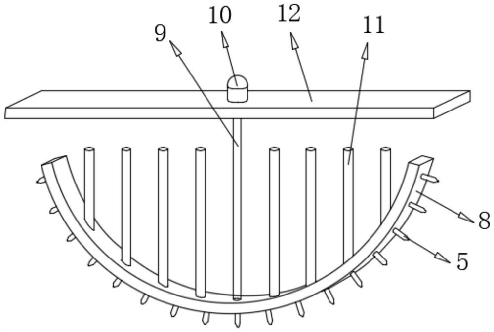
[0026] refer to Figure 1-2 , a stirring device for construction engineering, comprising a base 1, the top of the base 1 is slidably connected with a rotating plate 4, and the top of the rotating plate 4 is connected with a column through fastening bolts, and the top of the column is connected with a mounting ring 16 through fastening bolts , the top middle position of the mounting ring 16 is provided with a first perforation, and the inner walls of both sides of the first perforation are connected with the same stirring tank 13 through bearings, the inside of the stirring tank 13 is provided with a stirring mechanism, and the outer wall of one side of the stirring tank 13 The bottom is connected with the side wings 3 by fastening bolts, and the top of the rotating plate 4 is provided with a cam mechanism. While stirring the materials in the stirring tank 13 through the stirring mechanism, the side wings 3 can be knocked back and forth through the cam mechanism, thereby driving...

Embodiment 2

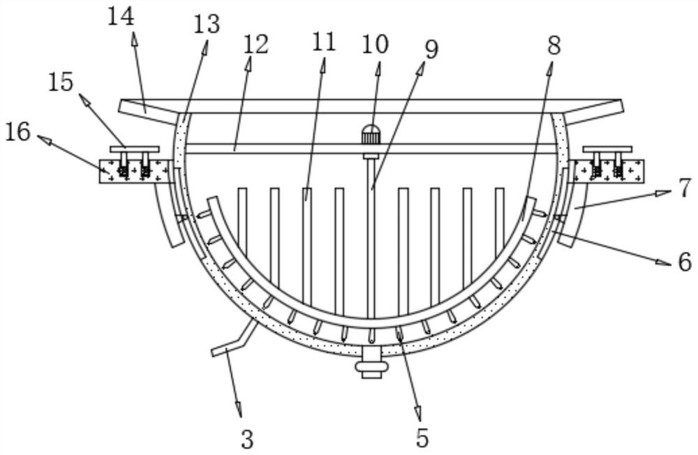
[0037] refer to image 3 , a stirring device for construction engineering. Compared with Embodiment 1, the bottom of the installation ring 16 is connected with extension plates 7 by fastening bolts along both sides of the first perforated opening, and the two extension plates 7 are close to the stirring One side of the tank 13 is connected with projections by fastening bolts, and the outer walls of both sides of the stirring tank 13 are provided with guide grooves 6 , and the outer diameter of the projections matches the inner diameter of the guide grooves 6 .

[0038] Working principle: While stirring the materials in the stirring tank 13 through the stirring mechanism, the cam mechanism can be used to reciprocate and strike the side wings 3, thereby driving the stirring tank 13 to swing back and forth, so that the materials are stirred with the stirring tank 13 at the same time. , to improve the stirring effect, the stirring motor 10 can be used to drive the stirring paddle ...


PUM


Abstract

The invention discloses a stirring device for constructional engineering. The stirring device comprises a base, a rotating plate is slidably connected with the top of the base, and a stand column is arranged at the top of the rotating plate; a mounting ring is arranged at the top of the stand column, a first through hole is formed in the middle of the top of the mounting ring, and the inner wallsof the two sides of the first through hole are connected with the same stirring groove through bearings; a stirring mechanism is arranged in the stirring groove, and a side wing is arranged at the bottom of the outer wall of one side of the stirring groove; a cam mechanism is arranged at the top of the rotating plate; the stirring mechanism comprises a stirring motor, a rotating shaft, a stirringpaddle, a fixing rod and a mounting rod; and the same mounting rod is arranged at the tops of the inner walls of the two sides of the stirring groove. According to the stirring device for constructional engineering, while materials in the stirring groove are stirred through the stirring mechanism, the side wing can be knocked in a reciprocating mode through the cam mechanism, so that the stirringgroove is driven to swing in a reciprocating mode, the materials are turned over along with swing of the stirring groove while being stirred, and the stirring effect is improved.

Description

technical field [0001] The invention relates to the technical field of construction engineering, in particular to a stirring device for construction engineering. Background technique [0002] The mixing device for construction engineering is a kind of construction engineering machinery, which is mainly used for mixing cement, sand, various dry powder mortar and other construction materials. This is a machine in which a shaft with blades rotates in a cylinder or tank to agitate and mix various ingredients into a mixture or consistency. [0003] After retrieval, the Chinese Patent Publication No. is CN208975672U, which discloses a stirring device for construction engineering, including a base plate, the upper surface of the base plate is provided with an arc-shaped groove, and the upper surface of the base plate passes through the fixed seat and the motor a machine. The lower surface of the body is fixedly connected, the motor a is electrically connected to an external power ...

Claims


Application Information

Patent Timeline
Patent Type & Authority Applications(China)
IPC IPC(8): B28C5/48
CPCB28C5/485
Inventor 朱皓
Owner 朱皓
Why Eureka
Try Eureka