Feeding mechanism with anti-blocking function for injection molding machine

A technology of injection molding machine and function, applied in the field of feeding mechanism for injection molding machine, can solve problems such as troublesome time-consuming, manual cleaning, easy to cause blockage, etc., to improve functionality, ensure stability and smoothness, and change feeding height. Effect

Inactive Publication Date: 2021-01-12
李香妹
View PDF11 Cites 2 Cited by
  • Summary
  • Abstract
  • Description
  • Claims
  • Application Information

AI Technical Summary

Problems solved by technology

[0004] The purpose of the present invention is: in order to solve the problem that the height of the feeding device of the traditional injection molding machine cannot be adjusted, and when the height of the feeding material changes, it cannot be used, and the scope of application is small. At the same time, no anti-blocking structure is installed inside, resulting in In the normal use process, due to the accumulation of materials or the excessive addition of materials, it is easy to be blocked, causing the device to fail to work normally, requiring manual cleaning, troublesome and time-consuming, and reducing work efficiency. The proposed one has anti-blocking function Feeding mechanism for injection molding machine

Method used


Image

  • Feeding mechanism with anti-blocking function for injection molding machine
  • Feeding mechanism with anti-blocking function for injection molding machine
  • Feeding mechanism with anti-blocking function for injection molding machine

Examples


Embodiment Construction

[0039] The following will clearly and completely describe the technical solutions in the embodiments of the present invention with reference to the accompanying drawings in the embodiments of the present invention. Obviously, the described embodiments are only some, not all, embodiments of the present invention. Based on the embodiments of the present invention, all other embodiments obtained by persons of ordinary skill in the art without creative efforts fall within the protection scope of the present invention.

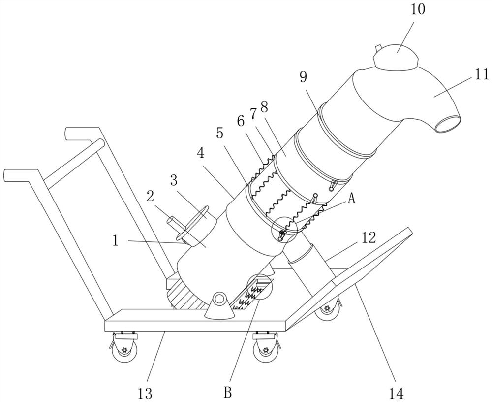
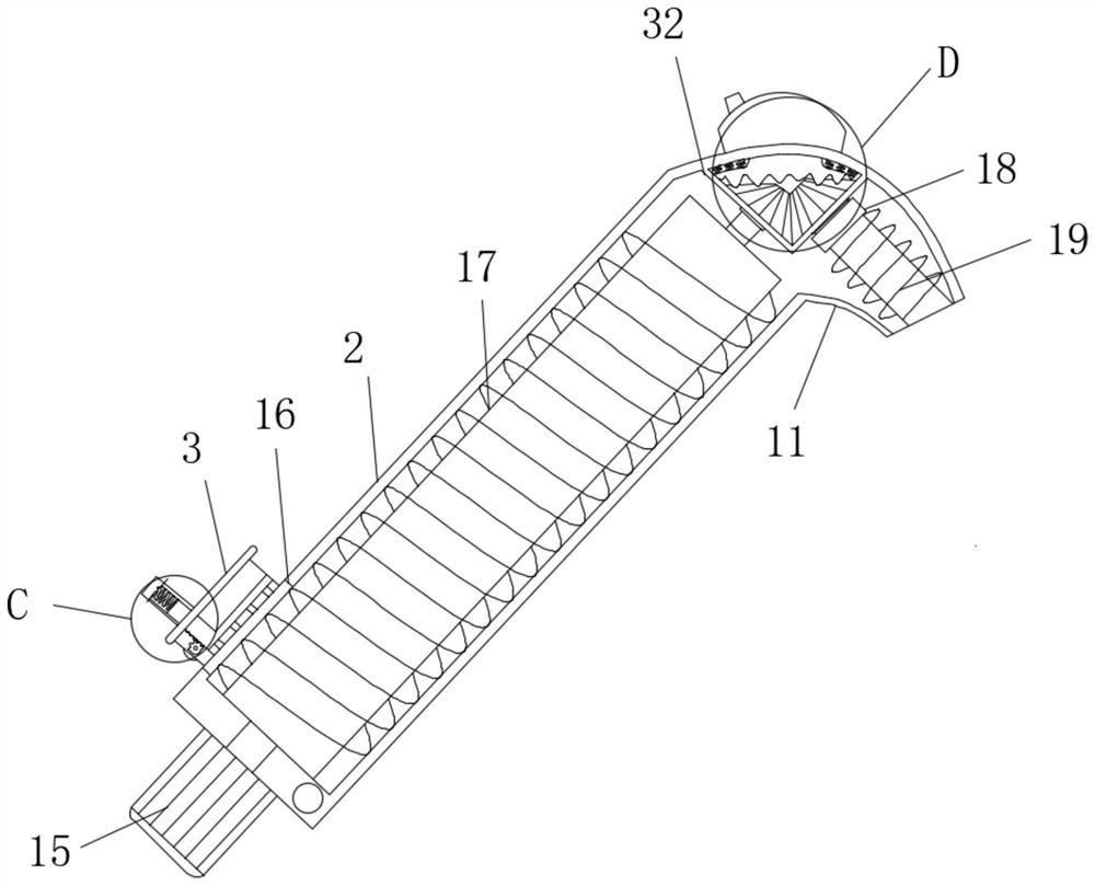
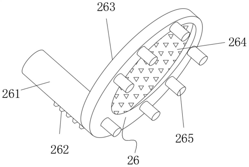
[0040] see Figure 1-7 , the present invention provides a technical solution: a feeding mechanism for an injection molding machine with an anti-blocking function, including a feeding outer cylinder 2, a first cleaning sleeve 4, a second cleaning sleeve 8, a cylinder 12, a base 13, a feeding Screw rod 17, fixing assembly 20, vibrating screen dredging assembly 26 and driving bevel gear 30, on the base 13, a material delivery outer cylinder 2 is installed on the base ...


PUM


Abstract

The invention discloses a feeding mechanism with an anti-blocking function for an injection molding machine, and belongs to the technical field of injection molding machines. The feeding mechanism comprises a material conveying outer cylinder, a first cleaning sleeve, a second cleaning sleeve, an air cylinder, a base, a material conveying screw rod, a fixing assembly, a vibrating screen dredging assembly and a driving bevel gear, wherein the material conveying outer cylinder is rotationally installed on the base through a mounting frame. According to the feeding mechanism, the vibrating screendredging assembly is installed in a feeding pipe, during feeding, a driving motor can be started, the driving motor can drive a driving half gear to rotate, the driving half gear can be meshed with meshing outer teeth of a top column, and the top column is driven to move; when the driving half gear can be disengaged from the meshing outer teeth of the top column, the vibrating screen dredging assembly can be reset due to the action of a second connecting spring, so that reciprocating vibration of the vibrating screen dredging assembly is realized; and a dredging bottom shaft is installed at the bottom of the vibrating screen dredging assembly, so that added materials can be screened at the same time, a feeding port can be effectively dredged, and the functionality of the device is improved.

Description

technical field [0001] The invention belongs to the technical field of injection molding machines, in particular to a feeding mechanism for injection molding machines with an anti-blocking function. Background technique [0002] The injection molding process is relatively common, and the injection molding machine is an indispensable device in the injection molding process. The injection molding machine is also called an injection molding machine or an injection machine. It is the main molding equipment for making thermoplastics or thermosetting plastics into various shapes of plastic products using plastic molding molds. Generally speaking, it can be divided into vertical type, horizontal type and all-electric type. The injection molding machine can heat the plastic when it is working, and apply high pressure to the molten plastic to make it inject and fill the mold cavity. When the injection molding machine is performing injection molding work, it often needs to feed it, a...

Claims


Application Information

Patent Timeline
Patent Type & Authority Applications(China)
IPC IPC(8): B29C45/18B29C45/17B29B13/10
CPCB29C45/18B29C45/17B29B13/10B29C2045/1784
Inventor 李香妹
Owner 李香妹
Why Eureka
Try Eureka