
A Calculation Method of Fuel Heat Generation at the Nozzle Hole of High Pressure Common Rail Injector

A high-pressure common rail and calculation method technology, which is applied in the direction of machines/engines, fuel injection control, electrical control, etc., can solve problems such as fuel temperature rise and fuel injection quantity prediction accuracy drop, and achieve accurate and precise prediction results

Active Publication Date: 2022-02-22
HARBIN ENG UNIV
View PDF4 Cites 0 Cited by
  • Summary
  • Abstract
  • Description
  • Claims
  • Application Information

AI Technical Summary

Problems solved by technology

In fact, when the high-pressure fuel is injected from the nozzle hole of the injector, the nozzle hole acts as an orifice, and the fuel with high pressure difference will cause the temperature of the fuel to rise after passing through the orifice, and the change of the fuel temperature will lead to the elasticity of the fuel. Changes in physical properties such as modulus, and the above-mentioned patents use unreasonable assumptions when estimating fuel injection volume, which may lead to a decline in the accuracy of fuel injection volume prediction

Method used


Image

  • A Calculation Method of Fuel Heat Generation at the Nozzle Hole of High Pressure Common Rail Injector
  • A Calculation Method of Fuel Heat Generation at the Nozzle Hole of High Pressure Common Rail Injector
  • A Calculation Method of Fuel Heat Generation at the Nozzle Hole of High Pressure Common Rail Injector

Examples


Embodiment Construction

[0023] The present invention is described in more detail below in conjunction with accompanying drawing example:

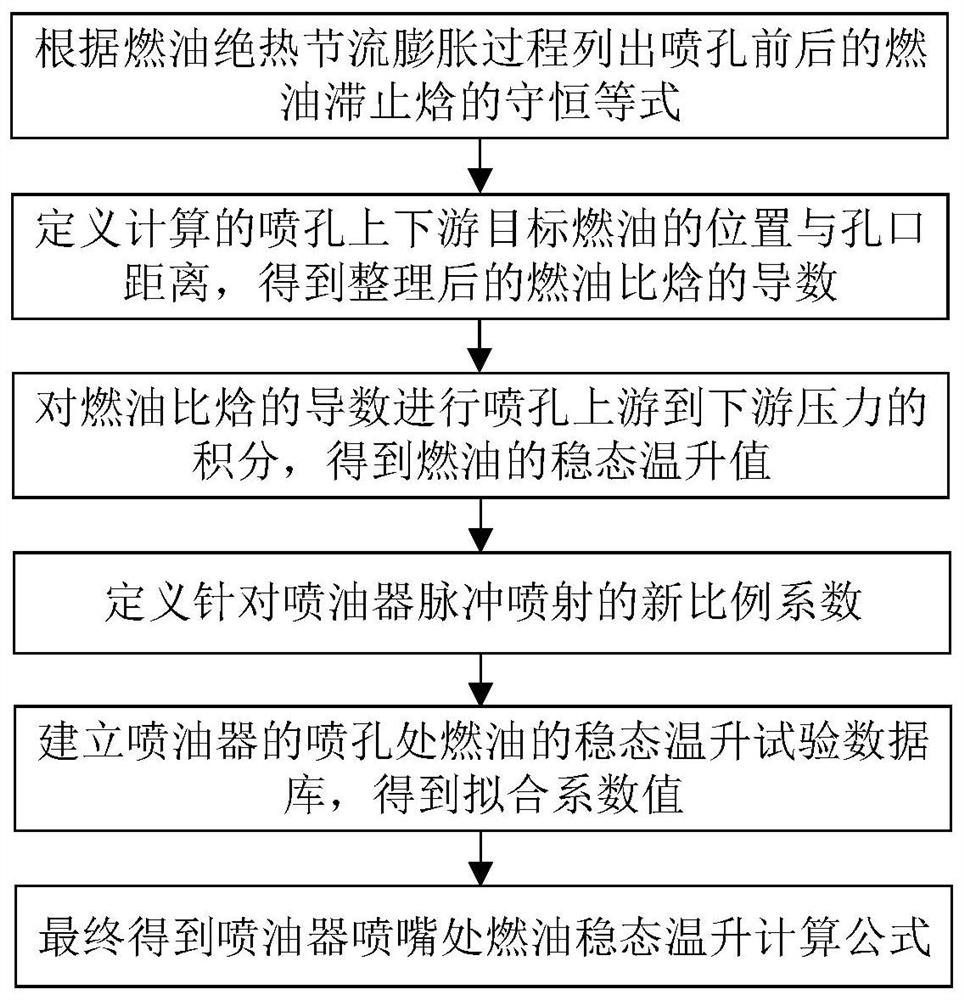
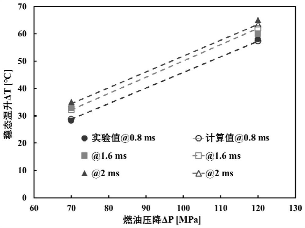
[0024] combine Figure 1-2 , the present invention is a method for calculating the steady-state temperature rise of fuel at the orifice of a high-pressure common rail injector, and the specific process includes:

[0025] (1) Assuming that the process of high-pressure fuel flowing through the nozzle hole in the common rail injector is an adiabatic throttling expansion process, according to the first law of thermodynamics, when there is no external work, the fuel stagnation enthalpy is conserved before and after the throttle hole:

[0026]

[0027] In the above formula, h is the specific enthalpy of fuel, which is a function of temperature T and pressure P, u is the flow velocity of fuel, and the subscripts up and dw represent the upstream and downstream of the injection hole, respectively.

[0028] (2) Define the distance between the upstream and downstream tar...


PUM


Abstract

The purpose of the present invention is to provide a method for calculating fuel heat generation at the nozzle hole of a high-pressure common rail injector, which includes the following steps: when there is no external work, the fuel stagnation enthalpy is conserved before and after the throttle hole, and the upstream and downstream of the nozzle hole are defined The position of the target fuel and the distance from the orifice, the temperature and the pressure are double derived, and the derivative of the specific enthalpy of the fuel is integrated from the upstream fuel pressure of the nozzle hole to the downstream fuel pressure, and the fuel steady state caused by the pressure difference between the upstream and downstream of the nozzle hole is obtained For temperature rise, a new coefficient is defined on the basis of considering the injection pulse width, and the steady-state temperature rise test database of the fuel at the nozzle hole is established when the injector is working under different injection pulse widths, and the data of the test database is extracted for fitting. Fuel heat generation value under different injection pulse width and injection pressure difference. The invention solves the technical problem that the prediction of the temperature rise in the injection hole cannot be realized. The calculation method provided can be coupled with the injection characteristic model of the common rail injector in real time to achieve a more accurate prediction of the cycle injection quantity.

Description

technical field [0001] The invention relates to a high-pressure common rail calculation method, in particular to a high-pressure common rail fuel heat generation calculation method. Background technique [0002] With environmental pollution and the depletion of fossil resources, higher thermal efficiency has become the goal pursued by the diesel engine industry. The high-pressure common rail fuel injection system has become an indispensable and important system for modern diesel engine fuel systems because it can realize that the injection characteristics do not depend on the engine operating conditions. The common rail injector is one of the important components of the high-pressure common rail system. When optimizing the design of the injector, more attention should be paid to the influence of structural parameters and control parameters on the injection characteristics. The patent "On-line Diagnosis Method of Common Rail Injector Consistency" calculates the actual amount...

Claims


Application Information

Patent Timeline
Patent Type & Authority Patents(China)
IPC IPC(8): F02D41/14F02D41/38
CPCF02D41/1486F02D41/38F02D2041/1412
Inventor 赵建辉卢相东
Owner HARBIN ENG UNIV
Learn More