Video monitoring device based on 5G network

A video monitoring and network technology, applied in the field of monitoring equipment, can solve the problems of blocking the camera's shooting line of sight, reducing the practicality, and dust, etc., to achieve the effect of ensuring clarity, avoiding condensation and frost, and ensuring cleanliness

Inactive Publication Date: 2021-01-12
夏喜明
View PDF10 Cites 3 Cited by
  • Summary
  • Abstract
  • Description
  • Claims
  • Application Information

AI Technical Summary

Problems solved by technology

[0007] In view of the above-mentioned shortcomings existing in the prior art, the present invention provides a video monitoring device based on a 5G network, which can effectively overcome the existing camera in the prior art, after long-term use, there will be more dust on the surface, Dust will affect the clarity of the camera, not only that, when the existing camera is used in severe cold areas, the surface will also condense frost, which will block the camera's shooting line of sight and reduce the practicability. At the same time, the existing camera is inconvenient to adjust From the perspective of monitoring, there are hidden dangers in actual use

Method used


Image

  • Video monitoring device based on 5G network
  • Video monitoring device based on 5G network
  • Video monitoring device based on 5G network

Examples


Embodiment 1

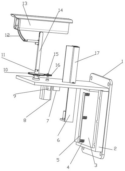
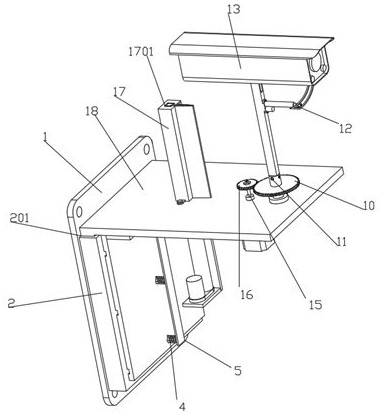
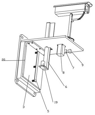
[0038] like Figure 1-8 A video monitoring device based on a 5G network is shown, including a mounting plate 1 and a camera 13, the left side wall of the mounting plate 1 is fixedly connected with a connecting plate 2, the connecting plate 2 is provided with a jack 201, and the connecting plate 2 passes through the jack 201 A second L-shaped plate 18 is plugged in, and the bottom of the second L-shaped plate 18 is provided with a spacer structure for fixing the position of the second L-shaped plate 18, and the second L-shaped plate 18 is provided on the left side wall of the space-limited structure. There is a dust removal structure for cleaning the camera 13. The dust removal structure includes a Z-shaped plate 6, a protective cover 17, a second electric push rod 19, a connecting rod 21, a mounting sleeve 22, a rubber sheet 23, a protective cover 17 and a Z-shaped plate 6 are all fixedly connected with the second L-shaped plate 18, the Z-shaped plate 6 is fixedly installed with...

Embodiment 2

[0040] Embodiment 2 is a further improvement to Embodiment 1.

[0041] like Figure 1-8 A video monitoring device based on a 5G network is shown, including a mounting plate 1 and a camera 13, the left side wall of the mounting plate 1 is fixedly connected with a connecting plate 2, the connecting plate 2 is provided with a jack 201, and the connecting plate 2 passes through the jack 201 A second L-shaped plate 18 is plugged in, and the bottom of the second L-shaped plate 18 is provided with a spacer structure for fixing the position of the second L-shaped plate 18, and the second L-shaped plate 18 is provided on the left side wall of the space-limited structure. There is a dust removal structure for cleaning the camera 13. The dust removal structure includes a Z-shaped plate 6, a protective cover 17, a second electric push rod 19, a connecting rod 21, a mounting sleeve 22, a rubber sheet 23, a protective cover 17 and a Z-shaped plate 6 are all fixedly connected with the secon...

Embodiment 3

[0043] Embodiment 3 is a further improvement to Embodiment 1.

[0044] like Figure 1-8 A video monitoring device based on a 5G network is shown, including a mounting plate 1 and a camera 13, the left side wall of the mounting plate 1 is fixedly connected with a connecting plate 2, the connecting plate 2 is provided with a jack 201, and the connecting plate 2 passes through the jack 201 A second L-shaped plate 18 is plugged in, and the bottom of the second L-shaped plate 18 is provided with a position-limiting structure for fixing the position of the second L-shaped plate 18. The position-limiting structure includes a first L-shaped plate 3, a spring 4, a pull Plate 5, movable triangular teeth 24, slide bar 25 and fixed triangular teeth 26, the left side wall of connecting plate 2 is evenly fixedly connected with fixed triangular teeth 26, and the left side wall of the first L-shaped plate 3 is evenly fixedly connected with Slide bar 25, the outer end of slide bar 25 is fixed...


PUM


Abstract

The invention relates to a video monitoring device based on a 5G network in the technical field of monitoring equipment. The video monitoring device comprises an installation plate and a camera, the installation plate is provided with a connection plate, the connection plate is provided with a jack, the connection plate is provided with a second L-shaped plate, the second L-shaped plate is provided with a limiting structure, the second L-shaped plate is provided with a horizontal rotating structure, the horizontal rotating structure comprises a driving motor, the driving motor is connected with the second L-shaped plate, the driving motor is provided with a rotating shaft, the rotating shaft is provided with a second gear ring, the second gear ring is provided with a first gear ring, the first gear ring is provided with a first rotating rod, the first rotating rod is provided with a straight rod, the straight rod is provided with an angle adjusting structure, and the angle adjusting structure comprises a protruding block and an arc-shaped plate, the arc-shaped plate and the protruding block are connected with the camera, and the protruding block is connected with the straight rod,a first electric push rod is provided with a connecting block, the connecting block is provided with a round rod, and an arc-shaped groove is formed in the arc-shaped plate and connected with the round rod. According to the video monitoring device, the monitoring direction of the camera is convenient to adjust, and the camera is convenient to flexibly adjust the direction for monitoring.

Description

technical field [0001] The invention relates to the technical field of monitoring equipment, in particular to a video monitoring device based on a 5G network. Background technique [0002] The fifth-generation mobile communication technology, referred to as 5G, is the latest generation of cellular mobile communication technology and an extension of 4G, 3G and 2G systems. The performance goals of 5G are high data rates, reduced latency, energy savings, cost reductions, increased system capacity, and large-scale device connectivity. In recent years, the fifth-generation mobile communication system 5G has become a hot topic in the communication industry and academia. There are two main driving forces for the development of 5G. [0003] With the rapid development of my country's social economy, the social environment is becoming more and more complex. Public security and public security incidents and violent incidents are frequent and frequent. Many factors have affected the l...

Claims


Application Information

Patent Timeline
Patent Type & Authority Applications(China)
IPC IPC(8): F16M13/02F16M11/04F16M11/18B08B1/00B08B1/02H04N5/225H04N5/232
CPCF16M13/02F16M11/045F16M11/12F16M11/18B08B1/02B08B1/008B08B1/005H04N7/185H04N23/50H04N23/695
Inventor 夏喜明
Owner 夏喜明
Why Eureka
Try Eureka