

Anti-freezing device and method for air energy water heater
An air energy water heater and anti-freezing device technology, which is applied in the directions of solar collectors, solar collector safety, solar collector controllers, etc. Faster melting time, faster heat loss, improved efficiency
- Summary
- Abstract
- Description
- Claims
- Application Information
AI Technical Summary
Problems solved by technology
Method used
Image

Examples
Embodiment 1
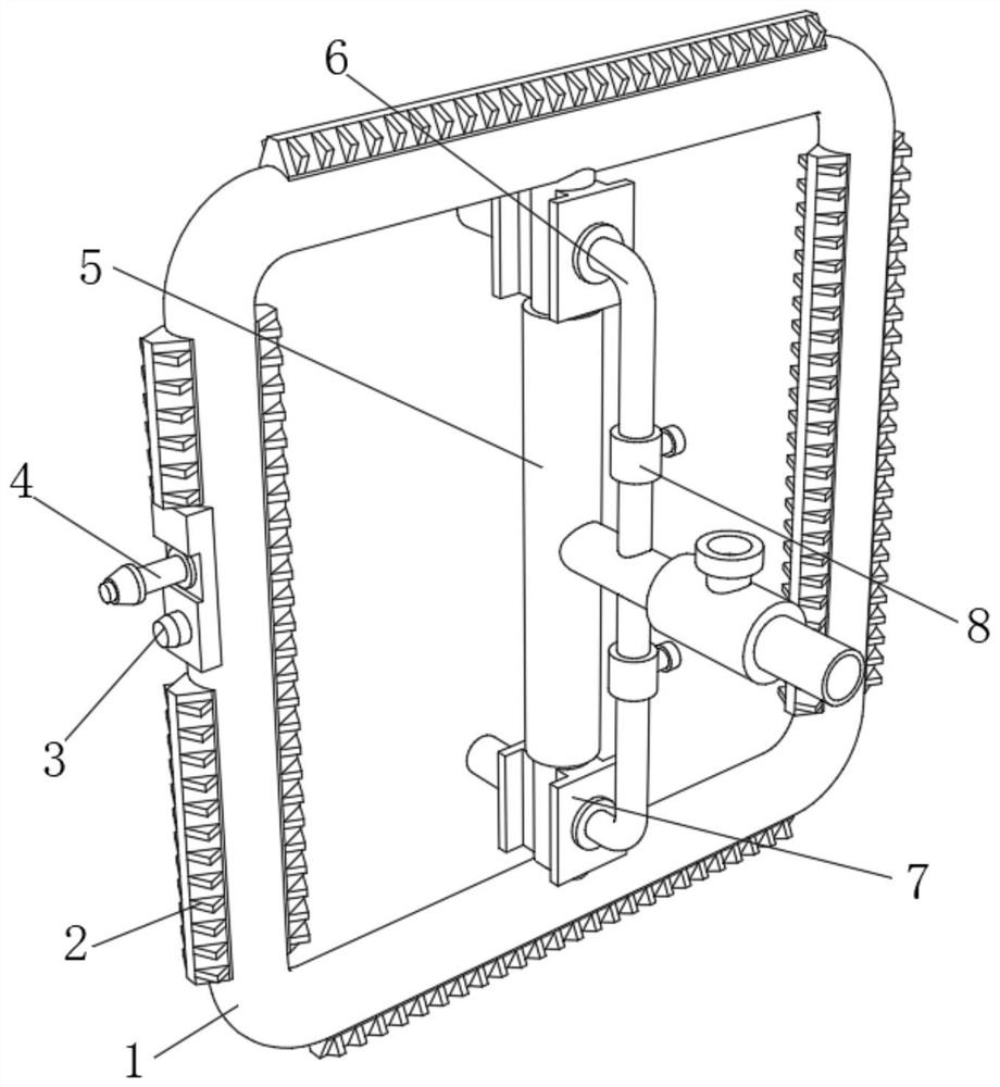
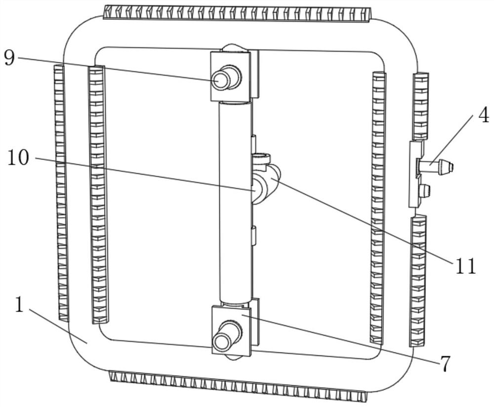
[0033] An antifreeze device for an air energy water heater, such as Figure 1-4 As shown, it includes an evaporating coil 1, one side of the outer wall of the evaporating coil 1 is fixed with a mounting plate by bolts, and one side of the outer wall of the mounting plate is fixed with a temperature sensor 4 through threads, and the mounting plate is close to a side below the temperature sensor 4. The side outer wall is fixed with a warning light 3 by bolts, and the top and bottom inner walls of the evaporating coil 1 are connected with the same guide tube 5 through threads respectively, and the circumferential outer walls at both ends of the guide tube 5 are respectively fixed with two symmetrical tubes by sealant. The anti-leakage gasket 7, and the outer walls of two anti-leakage gaskets 7 on the same side are respectively threadedly connected with a shunt pipe 6, and the outer wall of one side of the diversion pipe 5 is threadedly connected with a confluence pipe 10, and the ...
Embodiment 2
[0038] An antifreeze method for an antifreeze device of an air energy water heater, comprising the following steps:
[0039] S1: First, sense the temperature of the surrounding air through the temperature sensor 4, and monitor the surrounding temperature;
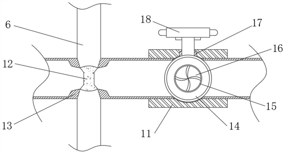
[0040] S2: When the temperature is lower than the preset value, the refrigerant flow path is realized by opening the solenoid valve, and the high-temperature and high-pressure refrigerant enters the guide pipe 5 through the manifold 10 from the compressor;
[0041] S3: When the refrigerant enters the manifold 10, start the electric valve stem 18 to drive the check ball 14 to rotate 90 degrees. The junction of the distribution pipe 6, and the elastic net 12 at the junction can effectively divide the refrigerant, so that its internal physical reorganization, at this time, the evaporator coil 1 is heated and the surrounding air is heated at the same time;
[0042] S4: At the same time, when the heat of the refrigerant in the ...
PUM
 Abstract
Description
Claims
Application Information