Position sensor, position determining method, and linear actuator

A technology of sensors and actuators, which is applied in the direction of converting sensor output, using electric/magnetic devices to transmit sensing components, electric/magnetic position measurement, etc., to achieve the effect of relative positions

Active Publication Date: 2021-01-12
EWELLIX AB
View PDF12 Cites 0 Cited by
  • Summary
  • Abstract
  • Description
  • Claims
  • Application Information

AI Technical Summary

Problems solved by technology

However, since the position change is not detected in the closed s...

Method used


Image

  • Position sensor, position determining method, and linear actuator
  • Position sensor, position determining method, and linear actuator
  • Position sensor, position determining method, and linear actuator

Examples


Embodiment Construction

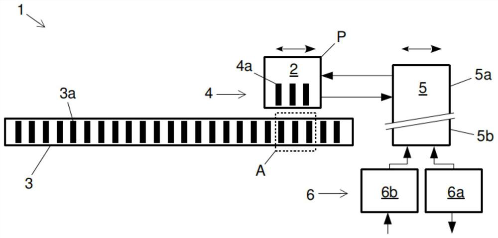
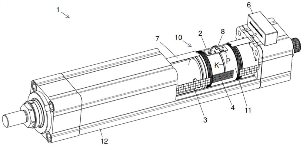
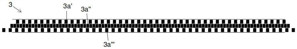
[0039] figure 1 An example of a position sensor 10 is shown, wherein the position sensor is used here to determine the position of the slide relative to the bushing of the linear actuator (see figure 2 ). The position sensor has a second sensor part with a reading unit 2 which is arranged to evaluate a capacitive signal regarding the position of the slide relative to the sleeve. For this purpose, the reading unit 2 is arranged on a slide, for example mounted on the slide, and the reading unit 2 can move together with the slide in the axial direction inside the sleeve. This is indicated by the double arrow above the reading unit 2 . Opposite the reading unit 2 , another part of the position sensor 10 , namely a first sensor part, is arranged on the bushing, said first sensor part being arranged to generate or at least influence a capacitive signal within the reading unit 2 . The first sensor part can be designed, for example, as a first electrode arrangement 3 which extends...


PUM


Abstract

The invention relates to a position sensor (10), a method for determining the position of a second sensor part of the position sensor (10) relative to a first sensor part of the position sensor (10),and a linear actuator (1). The second sensor component has an evaluation unit (2) which is designed to evaluate a capacitive signal relating to the position of the second sensor component relative tothe first sensor component (1). The position sensor (10) is further designed to provide an evaluation result at an interface of the first sensor component.

Description

technical field [0001] The invention relates to a position sensor, in particular for a linear actuator, a method for determining the position of a second sensor part of a position sensor relative to a first sensor part of a position sensor, and a linear actuator . Background technique [0002] Position sensors are used in many technical fields to determine the relative position of components or assemblies mounted movably relative to one another. Such mutually movably mounted components or assemblies occur, for example, in linear actuators, which are used in many technical systems to execute linear movements. An electric linear actuator generally consists of a motor and a gear driven by the motor, which transmits the rotary motion to the conversion element for converting the rotary motion into a linear motion of the linear unit. This conversion element can be, for example, a spindle, a chain, a belt or a toothed rack. [0003] For example, feedback on the position of the l...

Claims


Application Information

Patent Timeline
IPC IPC(8): G01D5/241G01B7/00G01B7/02
CPCG01D5/2415G01B7/003G01B7/02G01D5/241F16H25/2015H02K11/21H02K41/02H02K7/06
Inventor 克里斯托夫·里尔马塞尔·索尔特曼
Owner EWELLIX AB
Why Eureka
Try Eureka