Supercharge Your Innovation With Domain-Expert AI Agents!

Output driving circuit with electrostatic protection function

An output drive circuit, electrostatic protection technology, applied in the direction of logic circuit, logic circuit coupling/interface using field effect transistor, eliminating voltage/current interference, etc., can solve the problem of uneven conduction of NMOS and affect the ESD resistance of the output driver To achieve the effect of improving protection ability and improving ESD tolerance

Pending Publication Date: 2021-01-12
CHANGXIN MEMORY TECH INC
View PDF0 Cites 0 Cited by
  • Summary
  • Abstract
  • Description
  • Claims
  • Application Information

AI Technical Summary

Problems solved by technology

However, the existing circuit structure will cause uneven conduction between different NMOSs, which will affect the ESD tolerance of the output driver stage

Method used


Image

  • Output driving circuit with electrostatic protection function
  • Output driving circuit with electrostatic protection function
  • Output driving circuit with electrostatic protection function

Examples


Embodiment Construction

[0023] The specific implementation of the output drive circuit with electrostatic protection function provided by the present invention will be described in detail below in conjunction with the accompanying drawings.

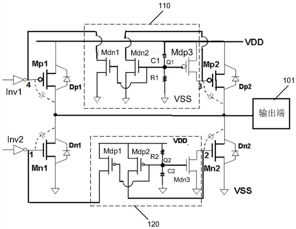
[0024] Please refer to figure 1 , is a schematic structural diagram of an output driving circuit according to a specific embodiment of the present invention.

[0025] The output driving circuit includes an output driving module, and the output driving module includes a first PMOS transistor Mp1 , a second PMOS transistor Mp2 , a first NMOS transistor Mn1 , a second NMOS transistor Mn2 , and an output terminal 101 .

[0026] The source of the first PMOS transistor Mp1 is connected to the power line VDD, and the drain is connected to the drain of the first NMOS transistor Mn1.

[0027] The source of the second PMOS transistor Mp2 is connected to the power line VDD, and the drain is connected to the drain of the second NMOS transistor Mn2.

[0028] Both the sourc...


PUM


Abstract

An output driving circuit comprises an output driving module which comprises a first PMOS tube, a second PMOS tube, a first NMOS tube, a second NMOS tube and an output end; the source electrode of thefirst PMOS tube is connected with a power line VDD, and the drain electrode of the first PMOS tube is connected with the drain electrode of the first NMOS tube; the source electrode of the second PMOS tube is connected to the power line VDD, and the drain electrode of the second PMOS tube is connected with the drain electrode of the second NMOS tube; the source electrode of the first NMOS transistor and the source electrode of the second NMOS transistor are connected to a ground wire VSS; the output end of the comparator is connected to the drains of the first PMOS tube and the first NMOS tube, and is also connected to the drains of the second PMOS tube and the second NMOS tube; the first potential control module is connected to the grid electrode of the first PMOS transistor and the gridelectrode of the second PMOS transistor and used for enabling the grid electrode of the first PMOS transistor and the grid electrode of the second PMOS transistor to have the same potential in the ESD state; and the second potential control module is connected to the grid electrode of the first NMOS transistor and the grid electrode of the second NMOS transistor, and is used for enabling the gridelectrode of the first NMOS transistor and the grid electrode of the second NMOS transistor to have the same potential in an ESD state.

Description

technical field [0001] The invention relates to the field of integrated circuits, in particular to an output drive circuit with an electrostatic protection circuit. Background technique [0002] Semiconductor integrated circuits must have electrostatic protection (ESD) protection circuits to ensure the reliability of integrated circuits. In order to save chip area, NMOS and PMOS in the output driver circuit of semiconductor integrated circuits have dual functions. On the one hand, they are used as the output driver stage of the circuit, and on the other hand, they can also be used as an ESD protection circuit when ESD occurs. [0003] In the prior art, the output driving circuit involved in the gate coupling technology is under the electrostatic discharge test, although the electrostatic voltage appearing on the output terminal will couple some voltage to the gate of the NMOS transistor through the parasitic capacitance between the gate and the drain. On, to force the NMOS ...

Claims


Application Information

Patent Timeline
IPC IPC(8): H03K19/003H03K19/0185H03K19/094
CPCH03K19/00361H03K19/018557H03K19/09432
Inventor 许杞安
Owner CHANGXIN MEMORY TECH INC
Features
  • R&D
  • Intellectual Property
  • Life Sciences
  • Materials
  • Tech Scout
  • Unparalleled Data Quality
  • Higher Quality Content
  • 60% Fewer Hallucinations
Learn More