
Stamping device for automobile chassis part production

A stamping device and automobile chassis technology, which is applied in the stamping field of auto parts, can solve problems such as easy splashing and staff injury

Pending Publication Date: 2021-01-15
赵敏
View PDF1 Cites 1 Cited by
  • Summary
  • Abstract
  • Description
  • Claims
  • Application Information

AI Technical Summary

Problems solved by technology

[0005] In order to solve the above-mentioned technical problems, the present invention provides a stamping device for the production of automobile chassis parts, so as to solve the problem that the scraps cut by stamping are prone to splash under the influence of pressure force when the existing automobile parts are stamped. , the splashed waste has a certain penetration force, which will cause harm to the staff around the equipment, and some parts are not made of steel, so the electromagnetic clamp will not be able to exert the fastening effect.

Method used


Image

  • Stamping device for automobile chassis part production
  • Stamping device for automobile chassis part production
  • Stamping device for automobile chassis part production

Examples


Embodiment

[0034] as attached figure 1 to attach Figure 11 Shown:

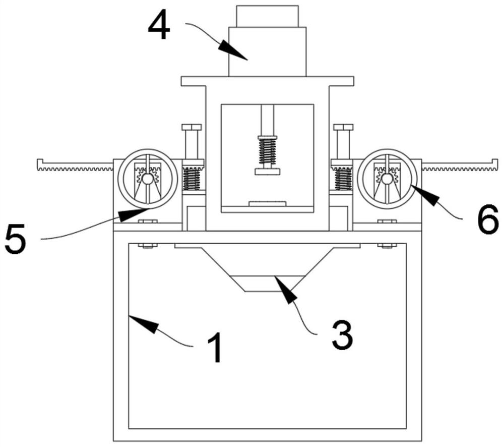
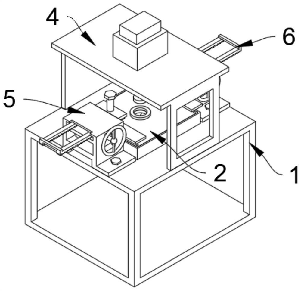
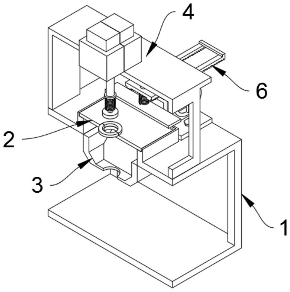
[0035]The present invention provides a stamping device for the production of automobile chassis parts, comprising: a support mechanism 1, a first limit mechanism 5, and a second limit mechanism 6, and the middle position of the top of the support mechanism 1 is fixedly connected with a platen mechanism 2; The middle position inside the mechanism 1 is fixedly connected with the top of the storage mechanism 3; the storage mechanism 3 includes a collection box 301, a collection tank 302, and a discharge hole 303. The discharge hole 303, the discharge hole 303 is connected with the collection tank 302; the middle position of the top of the bracket mechanism 1 is fixedly connected with the bottom of the stamping mechanism 4; The bottom of the position mechanism 6 is fixedly connected to the middle right side of the top of the bracket mechanism 1.

[0036] Wherein, the support mechanism 1 includes a support frame 101 and a...


PUM


Abstract

The invention provides a stamping device for automobile chassis part production, relates to the technical field of automobile part stamping, and solves the problem that when an existing automobile part is stamped, scraps cut off by stamping are prone to splashing under the influence of pressure acting force, the splashed scraps with certain penetrating forces will damage staff around the equipmentand an electromagnetic clamp cannot play a fastening role as some parts are not made of steel and iron materials. The stamping device for automobile chassis part production comprises a bracket mechanism, a first limiting mechanism and a second limiting mechanism, wherein a platen mechanism is fixedly connected to the middle of the top of the bracket mechanism. When the device is used, a part, needed to be stamped, of an automobile is placed on a placement plate, the position, needed to be stamped, of the part is located over an alignment hole, and at the moment, a worker rotates an annular disc at the front end of a rotating shaft A clockwise to enable a rack A to slide rightward.

Description

technical field [0001] The invention belongs to the technical field of stamping of automobile parts, and more specifically relates to a stamping device for the production of automobile chassis parts. Background technique [0002] Stamping is a method of forming and processing workpiece stamping parts of required shape and size by applying external force to plates, strips, pipes and profiles by presses and molds to cause plastic deformation or separation. Stamping and forging belong to plastic processing and are collectively called forging. The blanks for stamping are mainly hot-rolled and cold-rolled steel plates and steel strips. Among steel products all over the world, stamping processing is a production technology that uses the power of conventional or special stamping equipment to directly deform the sheet metal in the mold to obtain product parts of a certain shape, size and performance. [0003] For example, application number: CN201911212335.9 The present invention d...

Claims


Application Information

Patent Timeline
Patent Type & Authority Applications(China)
IPC IPC(8): B21D53/88B21D22/02B21D43/00B21D43/20B21D45/00B08B15/04B21D55/00
CPCB08B15/04B21D22/02B21D43/003B21D43/20B21D45/00B21D53/88B21D55/00
Inventor 赵敏
Owner 赵敏
Learn More