Convenient-to-open injection mold for gear part

A technology for injection molds and gear parts, which is applied to household appliances, other household appliances, applications, etc., and can solve the problems of occupation, inconvenience for mold opening and use, and large overall volume.

Inactive Publication Date: 2021-01-15
上海莎安精密注塑有限公司
View PDF5 Cites 3 Cited by
  • Summary
  • Abstract
  • Description
  • Claims
  • Application Information

AI Technical Summary

Problems solved by technology

[0004] In view of the above-mentioned related technologies, the inventor believes that although the above-mentioned injection mold opening device can quickly open the mold, the overall

Method used


Image

  • Convenient-to-open injection mold for gear part
  • Convenient-to-open injection mold for gear part
  • Convenient-to-open injection mold for gear part

Examples


Embodiment 1

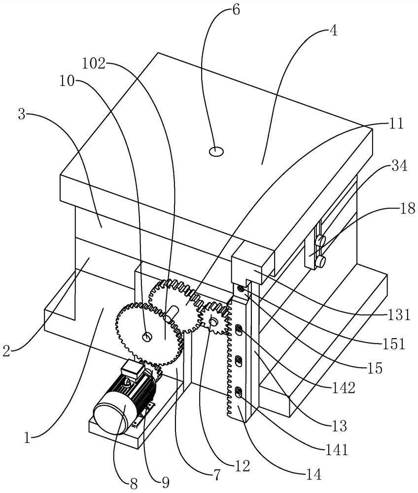
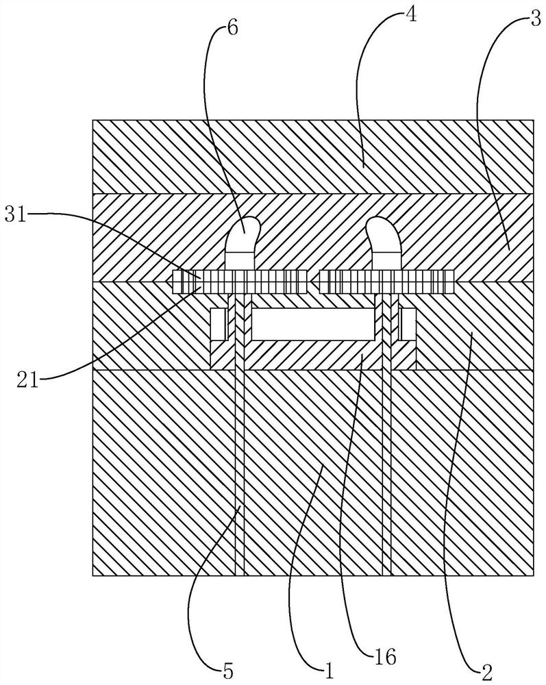
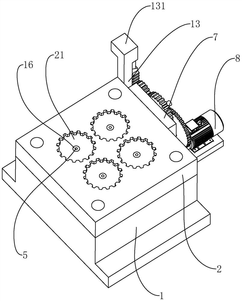
[0042] refer to figure 1 with figure 2 , an injection mold for gear parts that is convenient for mold opening, comprising a rear mold base 1, the rear mold base 1 is in a square shape. Rear mold core 2, front mold core 3 and front mold base 4 are arranged successively on the rear mold base 1, and the rear mold core 2, front mold core 3 and front mold base 4 are all in a square shape and correspond to the rear mold base 1. One end of the rear mold core 2 facing the front mold core 3 is provided with four rear mold cavities 21 , and the four rear mold cavities 21 are evenly distributed on the rear mold core 2 . A thimble 5 is slidably connected in the rear mold base 1 , and the end of the thimble 5 communicates with the cavity 21 of the rear mold. An end of the front mold core 3 close to the rear mold core 2 is provided with a front mold cavity 31 facing the rear mold cavity 21, and the front mold cavity 31 cooperates with the rear mold cavity 21 to form a gear shape that nee...

Embodiment 2

[0055] refer to Figure 5 with Figure 7 The difference between the second embodiment and the first embodiment is that the ejection mechanism 17 is different. The ejection mechanism 17 includes an ejection screw 173, and the ejection screw 173 is placed in the rear mold base 1 and is rotatably connected with the rear mold base 1. The end of the ejector screw 173 is placed in the ejector plate 16 and is threadedly connected with the ejector plate 16 , and the ejector screw 173 and the ejector plate 16 are perpendicular to each other. The other end of the ejecting screw 173 is fixedly provided with a worm gear 174 , and the end of the connecting shaft 10 is fixedly provided with a worm screw 175 engaged with the worm gear 174 , and the worm screw 175 is coaxial with the connecting shaft 10 . The connecting shaft 10 rotates, and then drives the worm 175 to rotate. Through the meshing connection between the worm 175 and the worm wheel 174, the rotation of the ejector screw 173 is...


PUM


Abstract

The invention relates to a convenient-to-open injection mold for a gear part. The injection mold comprises a back mold base; a back mold core, a front mold core and a front mold base are sequentiallyarranged on the back mold base; a back mold cavity is formed in the end, directly facing the front mold core, of the back mold core; a front mold cavity directly facing the back mold cavity is formedin the end, close to the back mold core, of the front mold core; a feeding opening communicates with the front mold cavity; a fixing plate is fixedly arranged on one side of the back mold core; a driving wheel and a lifting wheel are rotationally connected to the fixing plate; the driving wheel is connected with the lifting wheel; a driving motor is fixedly arranged on the fixing plate; an outputshaft of the driving motor is connected with the driving wheel; a connecting plate is arranged on one side of the front mold core; a lifting rack is arranged on the connecting plate; and the lifting rack is connected with the lifting wheel in a meshing manner. The driving wheel and the lifting wheel are driven to move through power driving of the driving motor, the lifting wheel is matched with the lifting rack, opening between the front mold cavity and the back mold cavity is achieved, and the injection mold has the effect of being rapidly opened in a limited space.

Description

technical field [0001] The present application relates to the field of injection molds, in particular to an injection mold for gear parts which is convenient for mold opening. Background technique [0002] Mold, various molds and tools used in industrial production for injection molding, blow molding, extrusion, die-casting or forging forming, smelting, stamping and other methods to obtain the required gear parts. In short, a mold is a tool used to make shaped objects. This tool is composed of various parts, and different molds are composed of different parts. It mainly realizes the processing of the shape of the article through the change of the physical state of the formed material. Known as the "mother of industry", it is a tool for turning blanks into workpieces with specific shapes and sizes under the action of external forces. [0003] The existing Chinese patent with the publication number CN109016413A discloses a mold opening device for injection molds, including a...

Claims


Application Information

Patent Timeline
IPC IPC(8): B29C45/26B29C45/40B29C45/66B29L31/32
CPCB29C45/26B29C45/4005B29C45/66B29L2031/322B29C2045/2683
Inventor 王威周涛查永国
Owner 上海莎安精密注塑有限公司
Why Eureka
Try Eureka