Fireproof cabinet and fireproof system
A technology of fireproof cabinets and fireproof partitions, applied in the field of fireproof safes, can solve the problems of short time, no fireproof ability, loss of people, etc., and achieve the effect of avoiding fire
- Summary
- Abstract
- Description
- Claims
- Application Information
AI Technical Summary
Problems solved by technology
Method used
Image
Examples
Embodiment 1
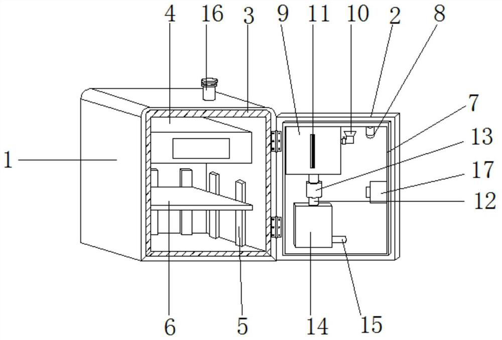
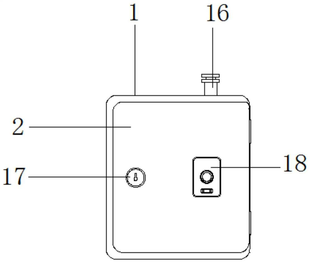
[0020] Embodiment 1, with reference to Figure 1-2 , a fireproof cabinet and a fireproof system, comprising the fireproof cabinet including a cabinet body 1, an opening is opened on the outer wall of one side of the cabinet body 1, and a cabinet door 2 is hinged on the inner wall of the opening, the inner wall of the cabinet body 1 and the The outer wall of the cabinet door 2 near the side of the cabinet body 1 is bonded with a fireproof interlayer 3. The fireproof system includes a fireproof mechanism installed on the outer wall of the side of the cabinet door 2 near the cabinet body 1. The fireproof mechanism includes a temperature sensor 8, a storage Box 9, feeding hopper 10, feeding pipe 12, atomizing box 14 and spray pipe 15, described storage box 9, feeding pipe 12, atomizing box 14 and spraying pipe 15 are connected successively from top to bottom, and discharging A flow control valve 13 is installed on the opposite side of the tube 12, a feeding hopper 10 is connected ...
Embodiment 2
[0022] Embodiment 2, with reference to Figure 1-2 , a fireproof cabinet and a fireproof system, comprising the fireproof cabinet including a cabinet body 1, an opening is opened on the outer wall of one side of the cabinet body 1, and a cabinet door 2 is hinged on the inner wall of the opening, the inner wall of the cabinet body 1 and the The outer wall of the cabinet door 2 near the side of the cabinet body 1 is bonded with a fireproof interlayer 3. The fireproof system includes a fireproof mechanism installed on the outer wall of the side of the cabinet door 2 near the cabinet body 1. The fireproof mechanism includes a temperature sensor 8, a storage Box 9, feeding hopper 10, feeding pipe 12, atomizing box 14 and spray pipe 15, described storage box 9, feeding pipe 12, atomizing box 14 and spraying pipe 15 are connected successively from top to bottom, and discharging A flow control valve 13 is installed on the opposite side of the tube 12, a feeding hopper 10 is connected ...
PUM
 Abstract
Description
Claims
Application Information
 - R&D
- Intellectual Property
- Life Sciences
- Materials
- Tech Scout
- Unparalleled Data Quality
- Higher Quality Content
- 60% Fewer Hallucinations
Browse by: Latest US Patents, China's latest patents, Technical Efficacy Thesaurus, Application Domain, Technology Topic, Popular Technical Reports.
© 2025 PatSnap. All rights reserved.Legal|Privacy policy|Modern Slavery Act Transparency Statement|Sitemap|About US| Contact US: help@patsnap.com


