Spring buffer type new energy automobile damping device
A technology for new energy vehicles and shock absorbers, applied in springs/shock absorbers, coil springs, leaf springs, etc., can solve problems such as poor shock absorption, loose parts, and potential safety hazards, saving resources and improving shock absorption effect of effect
- Summary
- Abstract
- Description
- Claims
- Application Information
AI Technical Summary
Problems solved by technology
Method used
Image

Examples
Embodiment 1
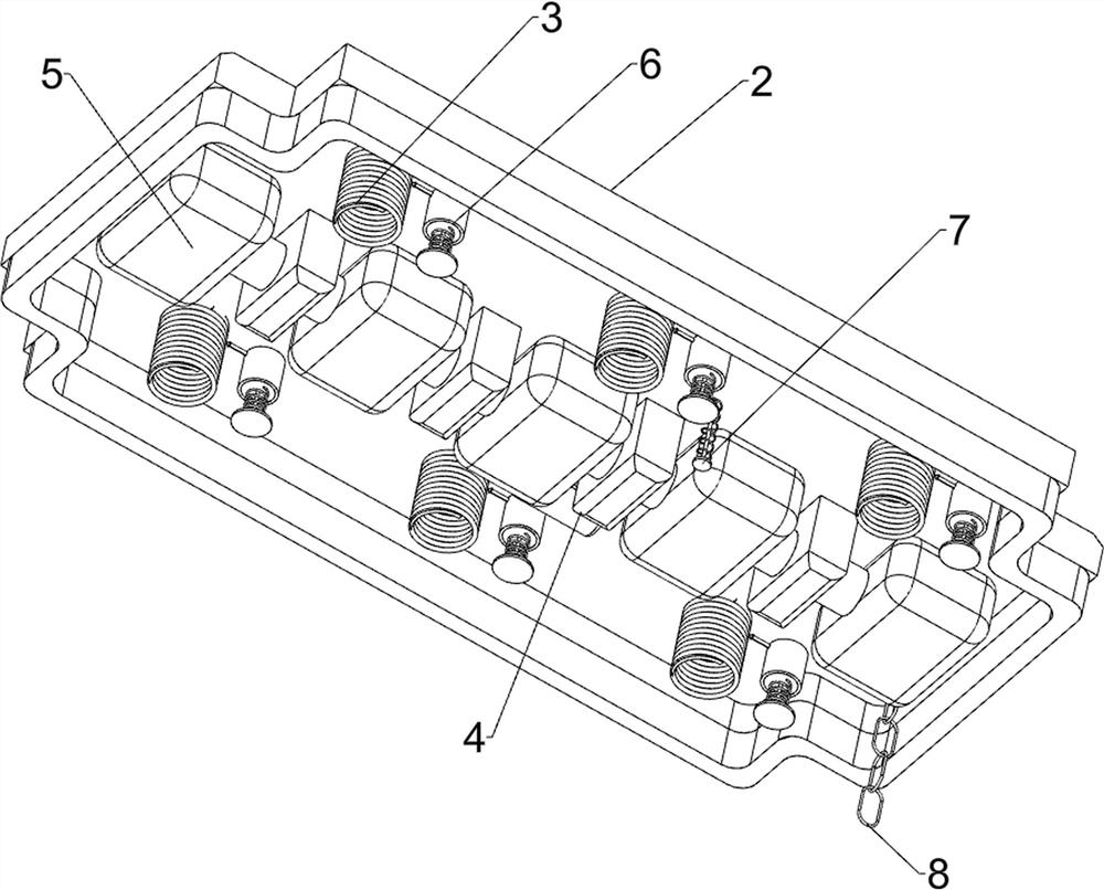
[0056]A spring buffer type new energy vehicle shock absorber, such asfigure 1 withfigure 2 As shown, it includes an automobile chassis 1, a support frame 2, a first shock-absorbing component 3, an air pump 4, and a second shock-absorbing component 5. The top of the automobile chassis 1 is provided with a first shock-absorbing component 3, and the top of the first shock-absorbing component 3 A support frame 2 is provided, an air pump 4 is provided at the bottom of the first damping assembly 3, a second damping assembly 5 is provided at the bottom of the first damping assembly 3, and the second damping assembly 5 is connected to the air pump 4.
[0057]The invention can be used to dampen small cars, and to a certain extent can increase the service life of the car. Automobile manufacturers can install the invention on the car chassis 1 of small cars. The elastic effect of the first shock absorption component 3 can reduce the car’s The collision between the chassis 1 and the support frame ...
Embodiment 2
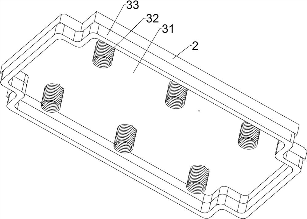
[0059]On the basis of Example 1, such asimage 3 withFigure 4 As shown, the first shock-absorbing assembly 3 includes a top plate 31, a first spring 32, and a rubber pad 33. The support frame 2 is provided with a top plate 31 slidably inside, and six first springs 32 are connected between the top plate 31 and the automobile chassis 1. , A rubber pad 33 is connected between the support frame 2 and the automobile chassis 1.
[0060]The reset function of the first spring 32 and the rubber pad 33 in the first shock absorption assembly 3 can absorb the shock of the car. When the car is driving on a bumpy road, the car chassis 1 will move up and down, and when the car chassis 1 moves up , Will make the first spring 32 and the rubber pad 33 compress, and then the reset function of the first spring 32 and the rubber pad 33 will drive the distance between the chassis 1 and the support frame 2 to increase slowly, when the chassis 1 moves downward , Will cause the first spring 32 and the rubber pa...
Embodiment 3
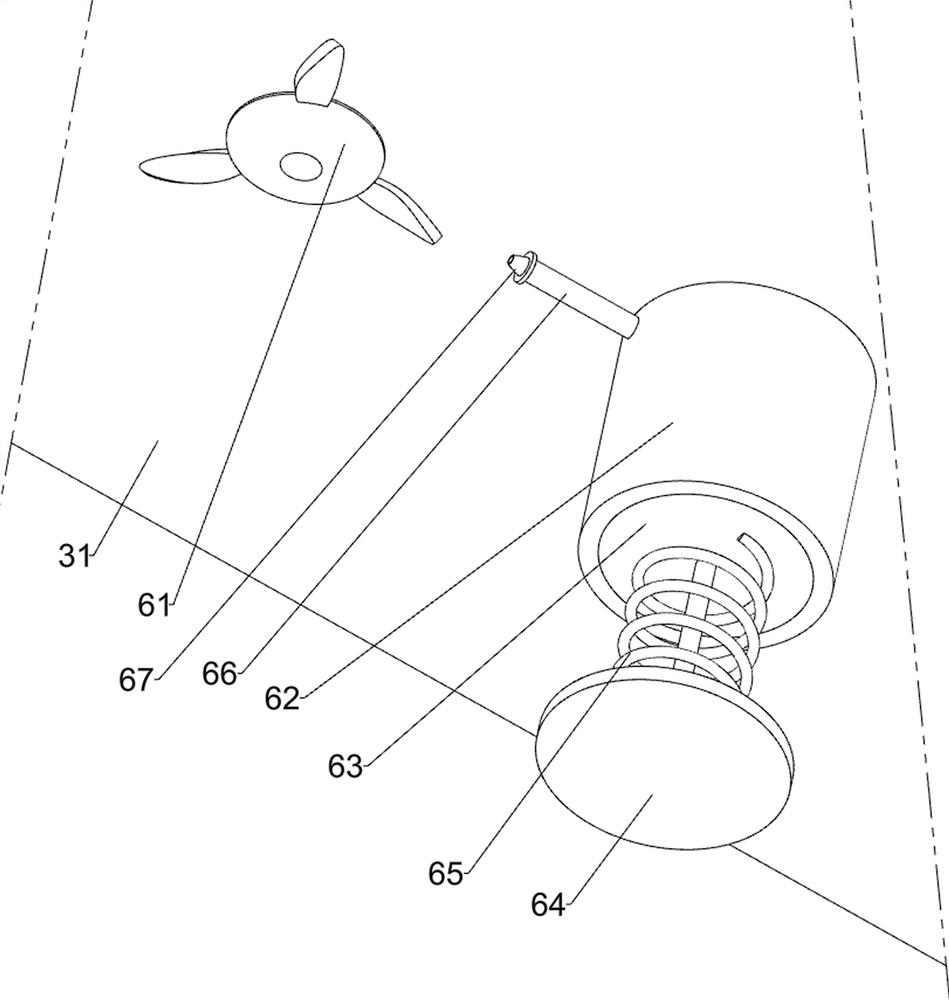
[0064]On the basis of Example 2, such asFigure 5 ,Figure 6 withFigure 7As shown, it also includes a cooling assembly 6. The cooling assembly 6 includes a fan 61, a cylinder 62, a baffle 63, a push plate 64, a second spring 65, a thin tube 66 and a nozzle 67. The bottom of the top plate 31 is evenly provided with six fans 61. The fan 61 is located inside the first spring 32. The bottom of the top plate 31 is evenly provided with six cylinders 62. The cylinders 62 are located on the rear side of the fan 61. The six cylinders 62 are slidably provided with a baffle 63 at the bottom of the baffle 63. In the push plate 64, a second spring 65 is connected between the cylinder 62 and the push plate 64. A thin tube 66 is provided on the upper part of each cylinder 62. The front side of the thin tube 66 is provided with a nozzle 67, and the nozzle 67 is facing the fan 61.
[0065]The cooling component 6 can dissipate heat to the first spring 32 to prevent the first spring 32 from being deformed ...
PUM
 Abstract
Description
Claims
Application Information
 - Generate Ideas
- Intellectual Property
- Life Sciences
- Materials
- Tech Scout
- Unparalleled Data Quality
- Higher Quality Content
- 60% Fewer Hallucinations
Browse by: Latest US Patents, China's latest patents, Technical Efficacy Thesaurus, Application Domain, Technology Topic, Popular Technical Reports.
© 2025 PatSnap. All rights reserved.Legal|Privacy policy|Modern Slavery Act Transparency Statement|Sitemap|About US| Contact US: help@patsnap.com