Extractor hood and control method of extractor hood

A range hood and range hood technology are applied in the removal of range hoods, heating methods, and household heating, etc., which can solve the problems of escaping fumes, escaping from fumes, and condensing and accumulating oil, so as to increase the speed of air intake on one side and avoid escaping of fumes. , The effect of preventing oil smoke from pouring back

Active Publication Date: 2021-01-15
NINGBO FOTILE KITCHEN WARE CO LTD
View PDF13 Cites 9 Cited by
  • Summary
  • Abstract
  • Description
  • Claims
  • Application Information

AI Technical Summary

Problems solved by technology

[0005] 1) After the range hood is installed with the cabinet, there will be a large gap between the cabinet and the fume collecting hood. This gap will make it easy for the oil fume to escape from here, and at the same time, the oil will condense on the cabinet;
[0006] 2) At present, commercial housing in the market is basically a public flue. In order to prevent the backflow of oil fume from the public flue, the range hood usually needs to be additionally installed with a check valve, resulting in a more complicated structure;
[0007] 3) At present, it is difficult for range hoods on the market to realize that the air inlet of the range hood is in the golden smoking area when cooking on one side or when the fire is large or small, or the smoke collecting hood is too small to effectively collect the smoke, which will cause smoke to escape when the user cooks with a large amount of oil fume. thereby affecting the user's health

Method used


Image

  • Extractor hood and control method of extractor hood
  • Extractor hood and control method of extractor hood
  • Extractor hood and control method of extractor hood

Examples


Embodiment Construction

[0047]The embodiments of the present invention will be described in detail below. Examples of the embodiments are shown in the accompanying drawings, wherein the same or similar reference numerals represent the same or similar elements or elements with the same or similar functions.

[0048]In the description of the present invention, it should be understood that the terms "center", "longitudinal", "transverse", "length", "width", "thickness", "upper", "lower", "front", " Back", "Left", "Right", "Vertical", "Horizontal", "Top", "Bottom", "Inner", "Outer", "Clockwise", "Counterclockwise", "Axial", The orientation or positional relationship indicated by "radial", "circumferential", etc. is based on the orientation or positional relationship shown in the drawings, and is only for the convenience of describing the present invention and simplifying the description, rather than indicating or implying the pointed device or element It must have a specific orientation, be constructed and operat...


PUM


Abstract

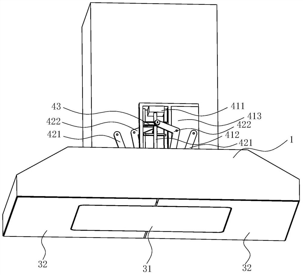
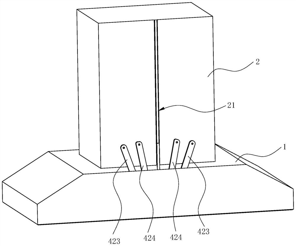
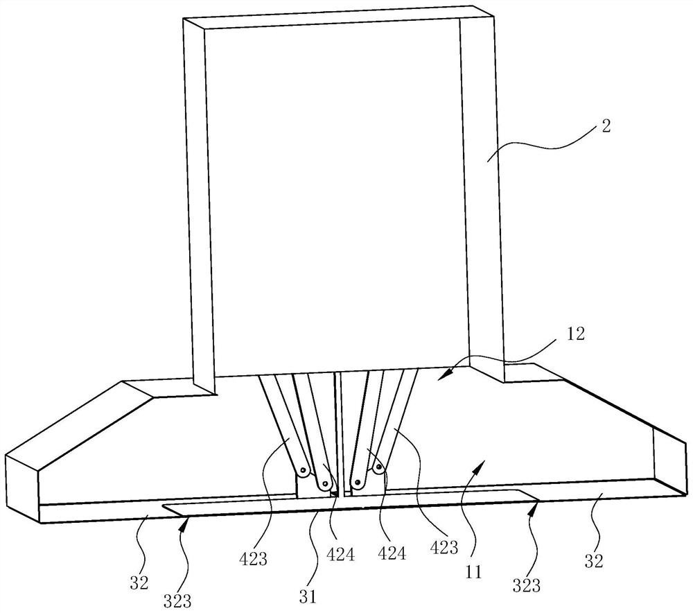
The invention discloses an extractor hood. The extractor hood comprises an exhaust fume collecting hood and an exhaust fume guide plate assembly, an exhaust fume collecting cavity is formed in the exhaust fume collecting hood, the exhaust fume collecting hood is open at the bottom of the exhaust fume collecting cavity, the exhaust fume guide plate assembly comprises an exhaust fume guide plate andtwo baffles, one baffle is at least partially located on the left side of the exhaust fume guide plate, and the other baffle is at least partially located on the right side of the exhaust fume guideplate; the extractor hood is characterized in that the exhaust fume guide plate can be located at a first position, the exhaust fume guide plate is located in the middle of the bottom of the exhaust fume collecting cavity at the moment and can also be located at a second position, and the exhaust fume guide plate is located below the exhaust fume collecting cavity at the moment; each baffle can belocated at a third position, and at the moment, the baffles extend to the middle of the upper surface of the exhaust fume guide plate from the left side or the right side of the bottom of the exhaustfume collecting hood; and each baffle can be located at a fourth position, and at the moment, the baffles are turned over to be separated from the exhaust fume guide plate. The invention further discloses a control method of the extractor hood.

Description

Technical field[0001]The invention relates to an oil fume purification device, in particular to a range hood, and a control method of the range hood.Background technique[0002]Range hoods have become one of the indispensable kitchen appliances in modern households. The range hood works by using the principle of fluid dynamics. A centrifugal fan installed inside the range hood sucks and exhausts the range hood, and uses a filter to filter some grease particles. The centrifugal fan includes a volute, an impeller installed in the volute, and a motor that drives the impeller to rotate. When the impeller rotates, negative pressure suction is generated in the center of the fan, and the oil fume under the range hood is sucked into the fan, and after being accelerated by the fan, it is collected by the volute and guided out of the room.[0003]Generally, range hoods include top-suction type and side-suction type, and top-suction type range hoods are more and more widely used due to the advanta...

Claims


Application Information

Patent Timeline
Patent Type & Authority Applications(China)
IPC IPC(8): F24C15/20
CPCF24C15/2021F24C15/2092
Inventor 童巧波邹志锋
Owner NINGBO FOTILE KITCHEN WARE CO LTD
Why Eureka
Try Eureka