
Concurrent mode synchronous measurement system and using method thereof

A technology of synchronous measurement and mode, applied in the electrical field, can solve the problems of low equipment utilization efficiency, low average single-channel transmission rate, and high customization cost

Active Publication Date: 2021-01-15
上海星秒光电科技有限公司
View PDF13 Cites 0 Cited by
  • Summary
  • Abstract
  • Description
  • Claims
  • Application Information

AI Technical Summary

Problems solved by technology

[0002] At present, in the measurement, most scenes have abandoned manual operation and use precision measurement equipment, but the existing measurement equipment, a device has multiple channels, because multiple channels generally share one interface to transmit data, so the average single-channel transmission The rate is relatively low, which affects the experimental results, and even some experiments cannot be carried out
For example, if a device has 64 or more channel solutions, the utilization efficiency of the device will be relatively low, and one device can only be used by one project personnel at the same time.
If a multi-channel customization solution is adopted, the customization cost is higher

Method used


Image

  • Concurrent mode synchronous measurement system and using method thereof
  • Concurrent mode synchronous measurement system and using method thereof
  • Concurrent mode synchronous measurement system and using method thereof

Examples


Embodiment Construction

[0038]The embodiments of the present disclosure will be described in detail below with reference to the accompanying drawings.

[0039]The following describes the implementation of the present disclosure through specific specific examples, and those skilled in the art can easily understand other advantages and effects of the present disclosure from the content disclosed in this specification. Obviously, the described embodiments are only a part of the embodiments of the present disclosure, rather than all the embodiments. The present disclosure can also be implemented or applied through other different specific embodiments, and various details in this specification can also be modified or changed based on different viewpoints and applications without departing from the spirit of the present disclosure. It should be noted that the following embodiments and the features in the embodiments can be combined with each other if there is no conflict. Based on the embodiments in the present dis...


PUM


Abstract

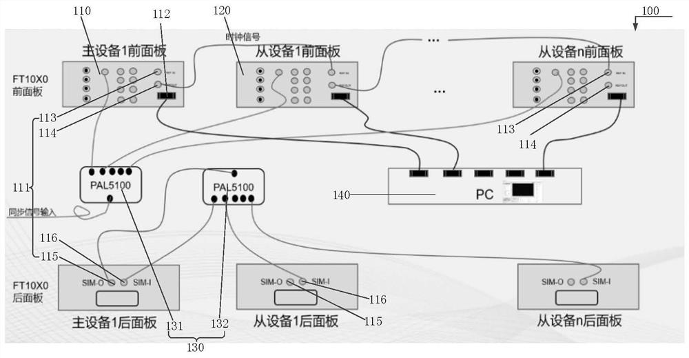
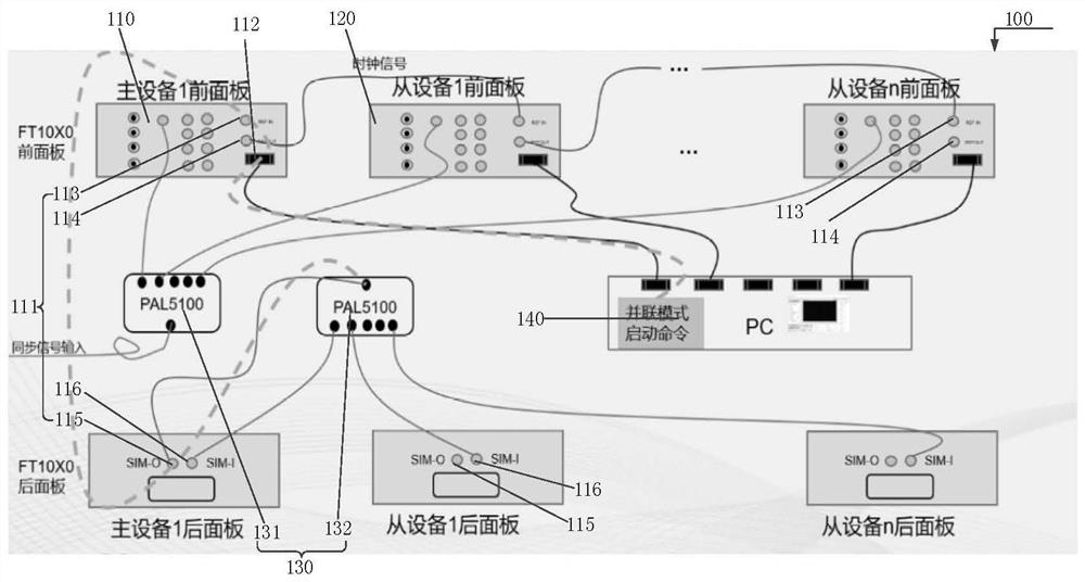
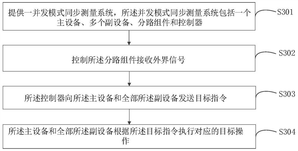
The embodiment of the invention provides a concurrent mode synchronous measurement system and a using method thereof, and belongs to the technical field of electricity. The system specifically comprises that main equipment and auxiliary equipment each comprise a data end and a control end, and the main equipment and all auxiliary equipment are connected in series through the data ends; a shunt assembly is used for transmitting received external signals and instructions to the main equipment and all the auxiliary equipment; the control end of the main equipment and the control ends of all the auxiliary equipment are electrically connected with a controller, the controller is electrically connected with the data end of the main equipment and the data ends of all the auxiliary equipment through the shunt assembly, and the controller is used for transmitting a starting instruction or a stopping instruction. According to the scheme of the invention, a plurality of pieces of equipment are adopted and are in concurrent networking connection through the shunt assembly, the corresponding number of channels can be selected according to different needs, the signal and instruction synchronization is realized through the shunt assembly, the utilization rate and the processing efficiency of the concurrent mode synchronous measurement system are improved, and the use cost is reduced.

Description

Technical field[0001]The present disclosure relates to the field of electrical technology, in particular to a concurrent mode synchronization measurement system and a method of use thereof.Background technique[0002]At present, in the measurement, most scenes have abandoned manual operation and used precision measurement equipment. However, the existing measurement equipment has multiple channels in one device. Since multiple channels generally share one interface for data transmission, the average single channel transmission is The rate is relatively low, which affects the effect of the experiment, and even some experiments cannot be performed. For example, if a device has 64 or more channel schemes, the utilization efficiency of the device will be relatively low, and an instrument can only be used by one project personnel at the same time. If a multi-channel customization solution is adopted, the customization cost is higher.[0003]It can be seen that there is an urgent need for a c...

Claims


Application Information

Patent Timeline
Patent Type & Authority Applications(China)
IPC IPC(8): G01R31/00
CPCG01R31/00Y02P90/02
Inventor 张帅郭强陈杰彭以新
Owner 上海星秒光电科技有限公司
Learn More