
Direct-current gear motor

A technology of DC deceleration motor and machine base, which is applied in the direction of electrical components, electromechanical devices, electric components, etc. It can solve the problems of easy failure of parts, vibration of motor, and influence on the stability of motor, so as to prolong the service life and avoid loose installation Effect

Pending Publication Date: 2021-01-15
SUZHOU XIANCHUAN MOTOR
View PDF0 Cites 0 Cited by
  • Summary
  • Abstract
  • Description
  • Claims
  • Application Information

AI Technical Summary

Problems solved by technology

[0004] The purpose of the present invention is to provide a DC geared motor to solve the problem that the motor proposed in the above background technology will vibrate during operation and affect the stability of the motor installation, and the internal parts of the motor are prone to failure under the influence of vibration for a long time The problem

Method used


Image

  • Direct-current gear motor
  • Direct-current gear motor
  • Direct-current gear motor

Examples


Embodiment

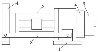
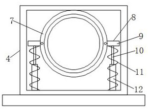
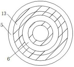
[0019] see Figure 1 to Figure 4 , the present invention provides a technical solution: a DC geared motor, including a machine base 1 and a machine body 2, a first outer ring 13 is provided on the surface of the machine body 2 opposite to the stable seat 4, and the outer surface of the first outer ring 13 is provided with There is a compression mechanism 14, the compression mechanism 14 includes a stable column 15, a second spring 16 and a moving column 17, the end of the moving column 17 away from the stable column 15 is provided with a moving ring 6, and the outside of the first outer ring 13 is provided with a second The outer ring 5 and the surface of the machine base 1 are symmetrically provided with a connecting plate 3, and a stabilizing seat 4 is provided between the ends of the two connecting plates 3 away from the machine base 1, the stabilizing seat 4 includes a vertical part and a horizontal part, and the stabilizing seat 4 The vertical part is provided with a roun...


PUM


Abstract

The invention discloses a direct-current gear motor. The direct-current gear motor comprises a motor base and a motor body, connecting plates are symmetrically arranged on the surface of the motor base, a stabilizing base is arranged between the ends, deviating from the motor base, of the two connecting plates, the stabilizing base comprises a vertical part and a horizontal part, and a round coverand a buffer mechanism are arranged on the vertical part of the stabilizing base; the buffer mechanism comprises a fixed block, a sliding column, a first spring and a fixed column, the sliding columnand the fixed column are in a vertical state, the bottom end of the fixed column is connected with the stabilizing base and embedded into the surface of the top end of the fixed column, and the top end of the sliding column is connected with the fixed block; and the motor body is connected with the round cover in a clamped mode, the end, deviating from the motor base, of the motor body is embedded into the round groove, and the stabilizing base is stabilized between the two connecting plates. When the motor operates, the motor body is vibrated, and the first spring buffers vibration borne bythe motor body, so that the motor body is kept in a stable state, motor installation loosening is avoided and faults caused by long-time vibration of internal parts of the motor are avoided.

Description

technical field [0001] The invention belongs to the technical field of electromechanical motor equipment, and in particular relates to a DC geared motor. Background technique [0002] DC deceleration motor, that is, gear deceleration motor, is based on the ordinary DC motor, plus a matching gear reducer. The function of the gear reducer is to provide a lower speed and a larger torque. The ratio can provide different speeds and torques, which greatly improves the utilization rate of DC motors in the automation industry. The geared motor refers to the integration of the reducer and the motor (motor). This integration is usually called a gear motor or a gear. Motors and geared motors are widely used in the steel industry, machinery industry, etc. The advantage of using geared motors is to simplify the design and save space. [0003] The existing motor will vibrate during operation and affect the stability of the motor installation. The internal parts of the motor are prone to ...

Claims


Application Information

Patent Timeline
IPC IPC(8): H02K5/24H02K5/10H02K7/00H02K7/10
CPCH02K5/10H02K5/24H02K7/003H02K7/10
Inventor 郑春福
Owner SUZHOU XIANCHUAN MOTOR
Learn More