Displacement device and magnetic levitation planar motor

A displacement device, the same technology, applied in the direction of electromechanical devices, magnetic attraction or thrust holding devices, electrical components, etc., can solve the problem of poor thrust accuracy of the workbench, low phase accuracy of the workbench, and different forces on the magnetic steel array and other issues to achieve the effect of increasing motion accuracy and reducing control difficulty

Active Publication Date: 2021-03-09
YINGUAN SEMICON TECH CO LTD
View PDF3 Cites 0 Cited by
  • Summary
  • Abstract
  • Description
  • Claims
  • Application Information

AI Technical Summary

Problems solved by technology

[0003] However, in the prior art, the direction of the magnetic steel array on the workbench and the coil is at an angle of 45 degrees, and the lengths of the multiple permanent magnets in the magnetic induction array are different, and the forces on each position of the magnetic steel array are different. The control brings a lot of trouble, and the phase accuracy is low, resulting in poor thrust accuracy of the workbench and poor movement accuracy of the workbench

Method used


Image

  • Displacement device and magnetic levitation planar motor
  • Displacement device and magnetic levitation planar motor
  • Displacement device and magnetic levitation planar motor

Examples


Embodiment 1

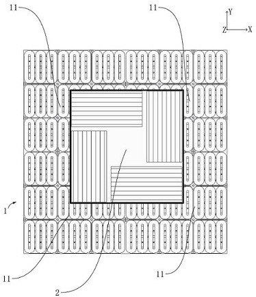
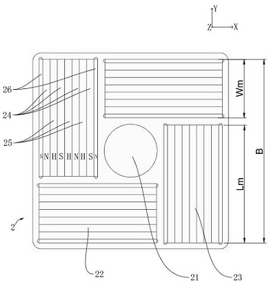
[0051] To solve the above problems, such as Figure 1-Figure 7 As shown, this embodiment provides a magnetic levitation planar motor, which includes a displacement device, and the displacement device includes a stator mechanism 1 and a working part 2 .

[0052] Specifically, in this embodiment, the stator mechanism 1 includes at least one module component 11, each module component 11 can generate a traveling wave magnetic field, the module components 11 have the same length in the X direction and the Y direction, and the X direction and the Y direction are orthogonal to each other. The number of rows and columns of the module assemblies 11 on the stator mechanism 1 are the same. The working part 2 is arranged above the stator mechanism 1, each module assembly 11 can generate a traveling wave magnetic field, and the traveling wave magnetic field interacts with the permanent magnetic field generated by the working part 2 to generate electromagnetic thrust, and the stator mechani...

Embodiment 2

[0066] In order to solve the problems in the prior art, this embodiment provides a magnetic levitation planar motor, including a displacement device, and the displacement device includes a stator mechanism 1 and a working part 2, and the structure of the magnetic levitation planar motor provided by this embodiment is basically the same as that of the first embodiment , only some differences exist in the structure of the module assembly 11, and this embodiment will not repeat the same structure as that of the first embodiment.

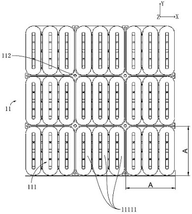
[0067] Such as Figure 8 As shown, the number of module assemblies 11 in this embodiment is four, and they are evenly arranged along the plane in a four-square grid pattern with two rows and two columns; each module assembly 11 includes at least nine coil array modules 111, arranged in three rows and three columns The Jiugongge pattern is evenly arranged along the plane. The difference between this embodiment and Embodiment 1 is that the coil array mod...

Embodiment 3

[0070] In order to solve the problems in the prior art, this embodiment provides a magnetic levitation planar motor, including a displacement device, and the displacement device includes a stator mechanism 1 and a working part 2, and the structure of the magnetic levitation planar motor provided by this embodiment is basically the same as that of the first embodiment In this embodiment, the same structure as that in Embodiment 1 will not be repeated.

[0071] In this example, if Figure 10 As shown, a plurality of module components 11 can be spliced ​​together, and the stator mechanism 1 can be provided with a plurality of working parts 2 according to usage requirements, and each working part 2 can work independently.


PUM


Abstract

The invention relates to the technical field of maglev planar motors, and discloses a displacement device and a maglev planar motor. The displacement device includes a stator mechanism and working parts, the stator mechanism includes at least one module component, the module component has the same length in the X direction and the Y direction, the number of rows and columns of the module component on the stator mechanism is the same, and the X direction and the Y direction are not parallel The working part is arranged above the stator mechanism, the working part includes a bearing platform and two first magnetic steel arrays and two second magnetic steel arrays installed on the bearing platform, the two first magnetic steel arrays extend along the X direction and The positions in the X direction are offset from each other, and there is a certain distance in the Y direction; the two second magnetic steel arrays extend along the Y direction and the positions in the Y direction are offset from each other, and there is a certain distance in the X direction; The first magnetic steel array and the second magnetic steel array are adjacently arranged in a staggered manner along the circumferential direction.

Description

technical field [0001] The invention relates to the technical field of maglev planar motors, in particular to a displacement device and a maglev planar motor. Background technique [0002] The magnetic levitation planar motor is usually divided into two parts, the stator mechanism and the mover assembly. In the X direction or the Y direction, the size of the stator mechanism is usually larger than the mover assembly, so as to provide a working area. These two parts are mainly composed of permanent magnets and energized coils, and the electromagnetic interaction between the two constitutes a 6-degree-of-freedom motion. Compared with traditional technology, it has no contact, no transmission, simple and compact structure, and high overall rigidity, which is conducive to achieving higher acceleration performance and positioning accuracy, and can be applied to vacuum or ultra-clean environments. [0003] However, in the prior art, the direction of the magnetic steel array on th...

Claims


Application Information

Patent Timeline
Patent Type & Authority Patents(China)
IPC IPC(8): H02K41/03H02N15/00
CPCH02K41/031H02N15/00
Inventor 胡兵蒋赟汤成燕
Owner YINGUAN SEMICON TECH CO LTD
Why Eureka
Try Eureka