Lifting device for electric power overhaul

A lifting device and power maintenance technology, applied in the direction of lifting device, lifting equipment safety device, etc., can solve the problems of hidden danger of tool safety, poor stability, time-consuming and laborious, etc., and achieve high safety performance, increased stability, and wide range of movement. Effect

Pending Publication Date: 2021-01-19
STATE GRID HENAN ELECTRIC POWER COMPANY ANYANG POWER SUPPLY
View PDF0 Cites 0 Cited by
  • Summary
  • Abstract
  • Description
  • Claims
  • Application Information

AI Technical Summary

Problems solved by technology

[0002] With the rapid development of electric power enterprises, the scale of the power grid has also gradually expanded. The progress of electric power engineering has made a great contribution to the promotion of economic growth. Inconsistency, different equipment sizes, maintenance personnel often need to reach different heights when working, and the tools usually used are ladders. When the ground is uneven, the ladder is difficult to fix and the stability is poor, and maintenance personnel usually need to carry tools. When climbing the ladder It is inconvenient to move, and the falling of tools is a safety hazard. When conditions permit, maintenance personnel can use the lifting platform for maintenance work. However, the existing lifting platform has a single function and can only provide standing functions. For vertical lifting operations, when horizontal movement is required, the lifting platform can only be lowered. The maintenance personnel walk off the platform, move the lifting platform to a suitable position and use it again. The moving process is difficult, time-consuming and labor-intensive, and may easily cause safety accidents.

Method used


Image

  • Lifting device for electric power overhaul
  • Lifting device for electric power overhaul
  • Lifting device for electric power overhaul

Examples


Embodiment 1

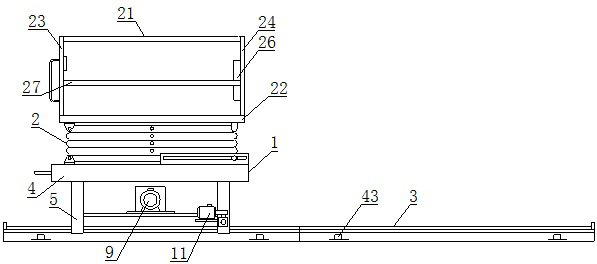
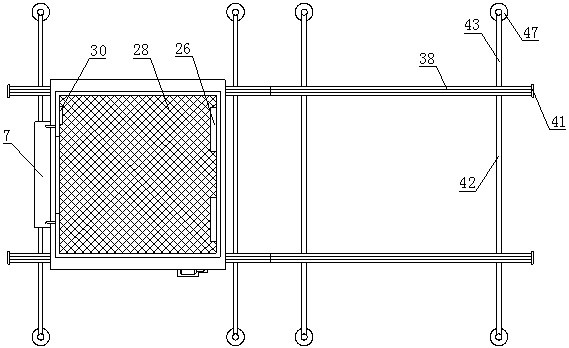
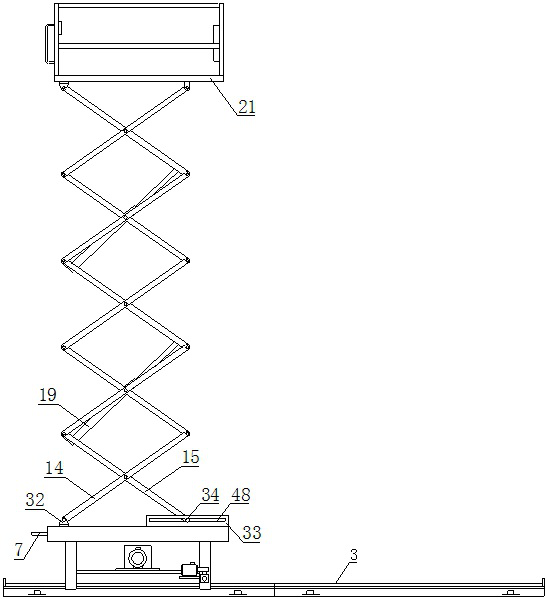
[0031] Such as Figure 1-13 As shown, a lifting device for electric power maintenance, which includes a base 1, a lifting frame 2 and a guide rail 3, the upper side of the base 1 is provided with a base plate 4, and the left part of the upper side of the base plate 4 is provided with a positioning block A32, The upper right part of the base plate 4 is provided with a limiting plate 33, the lower side of the base plate 4 is provided with a leg 5, the middle part of the leg 5 is provided with a connecting rod 6, and the connecting rod 6 is provided with a There is a carrier board 8, a hydraulic oil pump 9 is arranged on the upper side of the carrier board 8, a motor board 10 is arranged on the front side of the support leg 5, a drive motor 11 is arranged on the upper side of the motor board 10, and the A speed reducer 12 is arranged on the right side of the driving motor 11, a roller 13 is arranged at the lower end of the supporting leg 5, a lifting frame 2 is arranged on the up...

Embodiment 2

[0040] Such as Figure 1-13 As shown, a lifting device for electric power maintenance, which includes a base 1, a lifting frame 2 and a guide rail 3, the upper side of the base 1 is provided with a base plate 4, and the left part of the upper side of the base plate 4 is provided with a positioning block A32, The upper right part of the base plate 4 is provided with a limiting plate 33, the lower side of the base plate 4 is provided with a leg 5, the middle part of the leg 5 is provided with a connecting rod 6, and the connecting rod 6 is provided with a There is a carrier board 8, a hydraulic oil pump 9 is arranged on the upper side of the carrier board 8, a motor board 10 is arranged on the front side of the support leg 5, a drive motor 11 is arranged on the upper side of the motor board 10, and the A speed reducer 12 is arranged on the right side of the driving motor 11, a roller 13 is arranged at the lower end of the supporting leg 5, a lifting frame 2 is arranged on the up...


PUM


Abstract

The invention relates to a lifting device for electric power overhaul. The lifting device comprises a base, a lifting frame and guide rails, supporting legs are arranged on the lower side of the base,a hydraulic oil pump is arranged on the inner sides of the supporting legs, a driving motor is arranged on the front sides of the supporting legs, rolling wheels are arranged at the lower ends of thesupporting legs, the driving motor can drive the rolling wheels to rotate, the lifting frame is arranged on the upper portion of the base, and a hydraulic cylinder is arranged in the lifting frame. The hydraulic cylinder is driven by the hydraulic oil pump, a carrying table is arranged on the upper portion of the lifting frame, a controller is arranged in the carrying table, and the guide rails are arranged on the lower portion of the base. When the lifting device is used, a maintainer enters the carrying table and controls the lifting frame to reach a proper maintenance position through thecontroller; after the maintenance work is completed and the position needs to be adjusted, the driving motor needs to be controlled by the controller to operate to drive the base to move along the guide rails to reach other maintenance positions, and the lifting frame does not need to descend during movement, so that the working efficiency is greatly improved; and the lifting device has the advantages of being convenient to use, easy to control, wide in moving range and high in safety performance.

Description

technical field [0001] The invention belongs to the technical field of maintenance equipment, and in particular relates to a lifting device for electric power maintenance. Background technique [0002] With the rapid development of electric power enterprises, the scale of the power grid has also gradually expanded. The progress of electric power engineering has made a great contribution to the promotion of economic growth. Inconsistency, different equipment sizes, maintenance personnel often need to reach different heights when working, and the tools usually used are ladders. When the ground is uneven, the ladder is difficult to fix and the stability is poor, and maintenance personnel usually need to carry tools. When climbing the ladder It is inconvenient to move, and the falling of tools is a safety hazard. When conditions permit, maintenance personnel can use the lifting platform for maintenance work. However, the existing lifting platform has a single function and can on...

Claims


Application Information

Patent Timeline
Patent Type & Authority Applications(China)
IPC IPC(8): B66F11/04B66F17/00
CPCB66F11/042B66F17/006
Inventor 郭志红周静张占营赵宁宁
Owner STATE GRID HENAN ELECTRIC POWER COMPANY ANYANG POWER SUPPLY
Why Eureka
Try Eureka