Conductive via structure

一种导电通孔、导电垫的技术,应用在电路、电气元件、电固体器件等方向,能够解决限制装置微缩幅度、导电通孔结构难以达到设计规则等问题

Pending Publication Date: 2021-01-19
NAN YA TECH
View PDF8 Cites 0 Cited by
  • Summary
  • Abstract
  • Description
  • Claims
  • Application Information

AI Technical Summary

Problems solved by technology

However, the larger opening size also limits the miniaturization range of the device
As a result, it is also difficult to achieve the required design rules in the manufacture of conductive via structures

Method used


Image

  • Conductive via structure
  • Conductive via structure
  • Conductive via structure

Examples


Embodiment Construction

[0026] A number of implementations of the present invention will be disclosed below with the accompanying drawings. For the sake of clarity, many practical details will be described together in the following description. It should be understood, however, that these practical details should not be used to limit the invention. That is, in some embodiments of the present invention, these practical details are unnecessary. In addition, for the sake of simplifying the drawings, some well-known and commonly used structures and elements will be shown in a simple and schematic manner in the drawings. And if practically possible, the features of different embodiments can be used interchangeably.

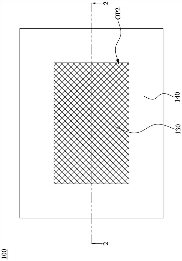
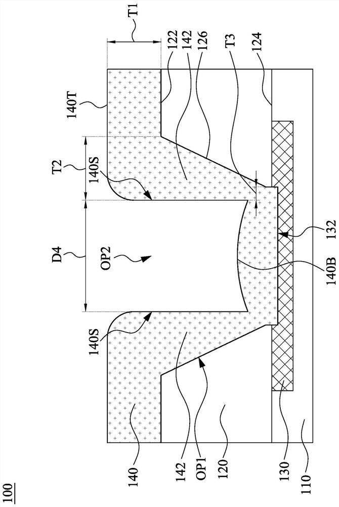
[0027] figure 1 is a top view of the conductive via structure 100 according to some embodiments of the present invention. figure 2 for along figure 1 A cross-sectional view of the conductive via structure 100 at the middle line segment 2-2. refer to figure 1 and figure 2 . The condu...


PUM


Abstract

The invention discloses a conductive via structure, including a first dielectric layer, a conductive pad, a second dielectric layer, and a redistribution layer. The conductive pad is in the first dielectric layer. The second dielectric layer is disposed above the first dielectric layer and has an opening. The conductive pad is in the opening. The opening has a first width at a top surface of the second dielectric layer and a second width at a bottom surface of the second dielectric layer. A difference between the first width and the second width is in a range from about 1.5 [mu]m to about 3 [mu]m. The redistribution layer extends from the top surface of the second dielectric layer to the conductive pad.

Description

technical field [0001] The invention relates to a conductive via structure. Background technique [0002] In the process of forming the redistribution layer through the aluminum deposition process, the aluminum particles will affect the efficiency of the subsequent process and the performance of the device. Therefore, in order to avoid the formation of particles, the temperature of the aluminum deposition process is controlled at a lower temperature. However, the lower temperature makes the thickness of the redistribution layer formed in the opening of the dielectric layer thinner. In addition, aluminum accumulations are formed on the upper ends of the openings, making the aluminum deposition efficiency worse. In this way, the quality of the electrical connection will be degraded. [0003] On the other hand, larger openings provide more space for aluminum to deposit into the openings. However, the larger opening size also limits the miniaturization range of the device. ...

Claims


Application Information

Patent Timeline
Patent Type & Authority Applications(China)
IPC IPC(8): H01L23/48H01L23/498H01L23/522H01L23/538
CPCH01L23/481H01L23/49827H01L23/5226H01L23/5384H01L23/49894H01L23/53214H01L24/02H01L2224/0239H01L2224/0235H01L2224/0236H01L24/13H01L2224/13024H01L2224/024H01L2224/0231H01L2224/131H01L2924/01013H01L2924/059H01L2924/05042H01L2924/05442H01L2924/00012H01L2924/00014H01L2924/014H01L21/486H01L23/291
Inventor 施信益
Owner NAN YA TECH
Why Eureka
Try Eureka