
Self-locking device for endoscope bend

A self-locking device and endoscope technology, applied in the fields of endoscope, application, medical science, etc., can solve the problems of poor locking effect, low convenience of the cover plate, and inability to improve the locking accuracy, so as to achieve high locking accuracy and improved The effect of adjusting precision

Pending Publication Date: 2021-01-22
丁思高普医疗系统有限公司
View PDF1 Cites 0 Cited by
  • Summary
  • Abstract
  • Description
  • Claims
  • Application Information

AI Technical Summary

Problems solved by technology

[0007] In order to solve the above-mentioned technical problems, the present invention provides a self-locking device for endoscope angles to solve the existing problem that the existing device can only achieve single-point locking during the adjustment process, and the locking effect is poor, and it is not enough to pass through. Structural improvement achieves multiple locking, and the improvement of locking accuracy cannot be achieved with structural improvement; moreover, the cover plate of the existing device is less convenient to fix and does not have the problem of automatic slag removal function

Method used


Image

  • Self-locking device for endoscope bend
  • Self-locking device for endoscope bend
  • Self-locking device for endoscope bend

Examples


Embodiment

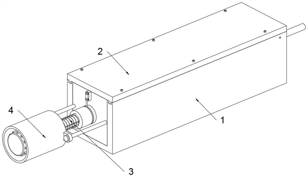
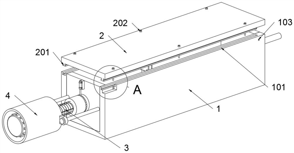
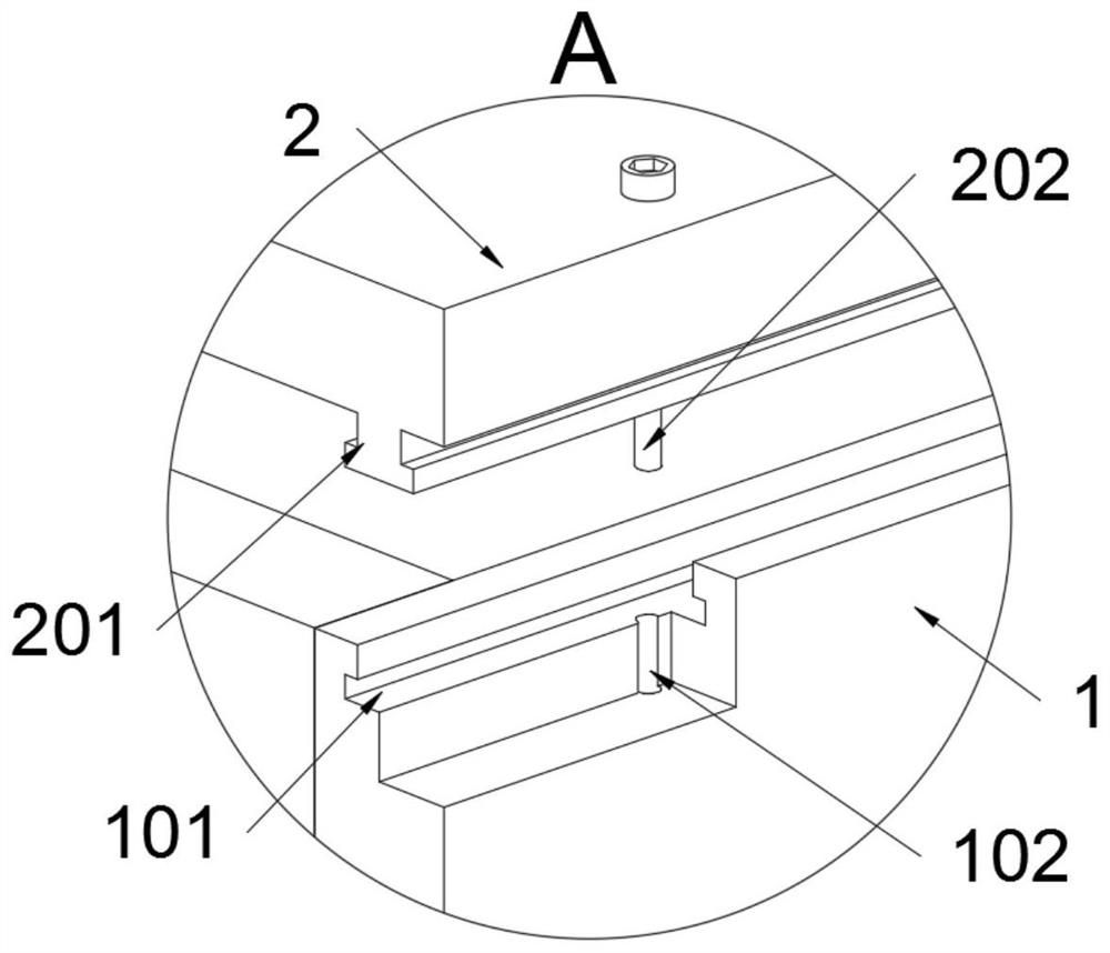
[0036] as attached figure 1 to attach Figure 9 Shown:

[0037] The invention provides a self-locking device for endoscope angles, including a box body 1; a cover plate 2 is fixedly connected to the box body 1, and an adjustment structure 3 is installed on the box body 1, and a Protective structure 4; see e.g. Figure 6 and Figure 7, the adjustment structure 3 includes the tooth row B311 and the elastic bayonet C312, the tooth row B311 is welded on the bottom surface of the connecting block 307; The tooth row B311 and the tooth row A309 are arranged in a staggered shape, and the tooth row B311 and the elastic bayonet C312 together form the second limit structure of the connecting block 307, so that auxiliary locking can be realized, and the locking locking can also be improved. The adjustment accuracy; refer to as Figure 4 , the protective structure 4 includes a sleeve 402, the sleeve 402 is sleeved on the threaded rod 301, and the sleeve 402 is a cover-shaped structure...


PUM


Abstract

The invention provides a self-locking device for an endoscope bend, and relates to the technical field of probe devices. The problems that a single-position locking effect is poor, multiple locking cannot be realized through structural improvement, the locking precision cannot be improved under the structural improvement, and an automatic slag removal function is not realized are solved. The self-locking device for the endoscope bend comprises a box body, a cover plate is fixedly connected to the box body, an adjusting structure is installed on the box body, and a protection structure is installed on the adjusting structure. Because an elastic bayonet lock B is fixedly connected to the inner wall of the box body, the head end of the elastic bayonet lock B is connected with a tooth row A ina clamped mode, and the elastic bayonet lock B and the tooth row A jointly form a limiting structure of a connecting block; and due to the fact that a tooth row B and the tooth row A are arranged ina staggered mode, and the tooth row B and an elastic bayonet lock C jointly form a second limiting structure of the connecting block, auxiliary locking can be achieved, and the adjusting precision ofclamping locking can be improved.

Description

technical field [0001] The invention belongs to the technical field of probe devices, and more specifically relates to a self-locking device for endoscope bending angles. Background technique [0002] The gastrointestinal tract is the largest immune organ in the human body, and it is also the largest detoxification organ in the human body. In recent years, gastric cancer, colon cancer, and esophageal cancer have become the top ten cancers in the incidence of malignant tumors. Observing the surface structure of the digestive tract mucosa is of great significance to the discovery and treatment of cancer. Endoscopy plays a key role in this field. It has been widely used in clinical treatment. [0003] For example, the application number: CN201810584433.4, the present invention discloses a rotatable probe bending structure for endoscopes. Including the probe end part and the traction handle part, the top cover tube and the bottom bracket sleeve are fixedly socketed, the bott...

Claims


Application Information

Patent Timeline
IPC IPC(8): A61B1/00A61B1/005
CPCA61B1/00064A61B1/00147A61B1/0055
Inventor 丁祥宏夏明成
Owner 丁思高普医疗系统有限公司
Learn More