
Stamping device capable of automatically correcting and stamping workpieces

A technology for stamping workpieces and stamping devices, which is applied in the direction of feeding devices, positioning devices, storage devices, etc., which can solve the problems of inability to meet the positioning of the plate, the inability to meet the requirements of machining accuracy, and the reduction of the pass rate of the processed plate, so as to improve the accuracy , improve the pass rate, and achieve the effect of precise positioning

Inactive Publication Date: 2021-01-22
吉安持凡电子科技有限公司
View PDF1 Cites 4 Cited by
  • Summary
  • Abstract
  • Description
  • Claims
  • Application Information

AI Technical Summary

Problems solved by technology

[0006] The purpose of the present invention is to provide a punching device for automatically correcting punched workpieces to solve the problem that the prior art punching device with automatic correction only uses two electric push rods on the side to push the plate to the punching position. Satisfy the positioning of the front and rear positions of the plate. When each plate needs to be precisely processed, only the positioning on the left and right sides cannot meet the processing accuracy requirements, which will lead to a problem that the pass rate of the processed plate will decrease.

Method used


Image

  • Stamping device capable of automatically correcting and stamping workpieces
  • Stamping device capable of automatically correcting and stamping workpieces
  • Stamping device capable of automatically correcting and stamping workpieces

Examples


Embodiment Construction

[0027] The following will clearly and completely describe the technical solutions in the embodiments of the present invention with reference to the accompanying drawings in the embodiments of the present invention. Obviously, the described embodiments are only some, not all, embodiments of the present invention. Based on the embodiments of the present invention, all other embodiments obtained by persons of ordinary skill in the art without creative efforts fall within the protection scope of the present invention.

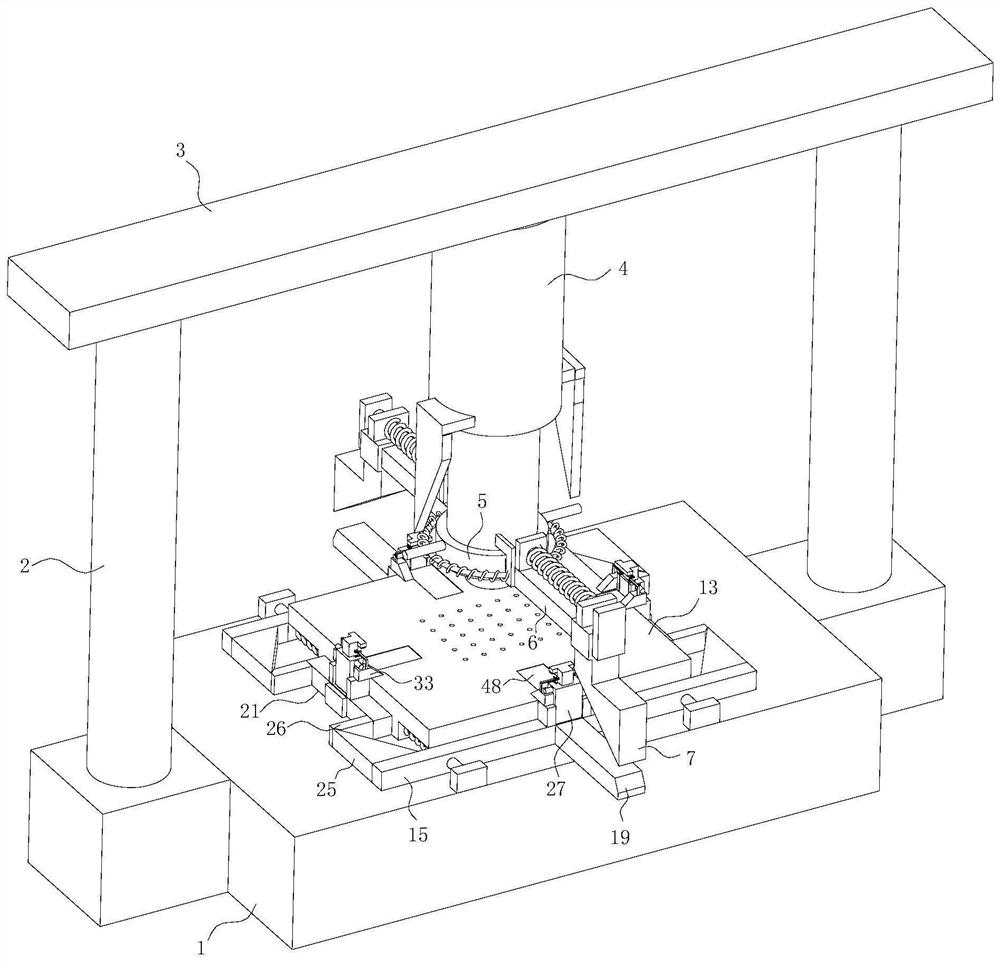
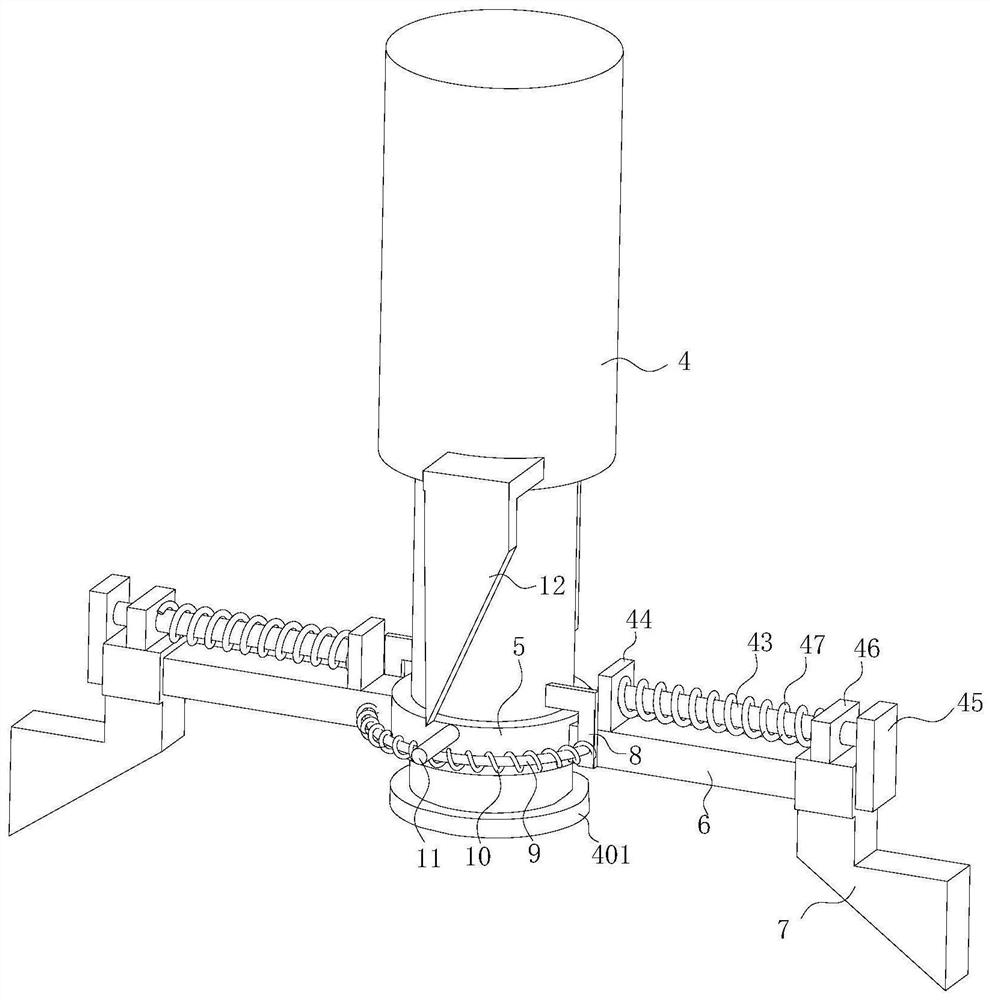
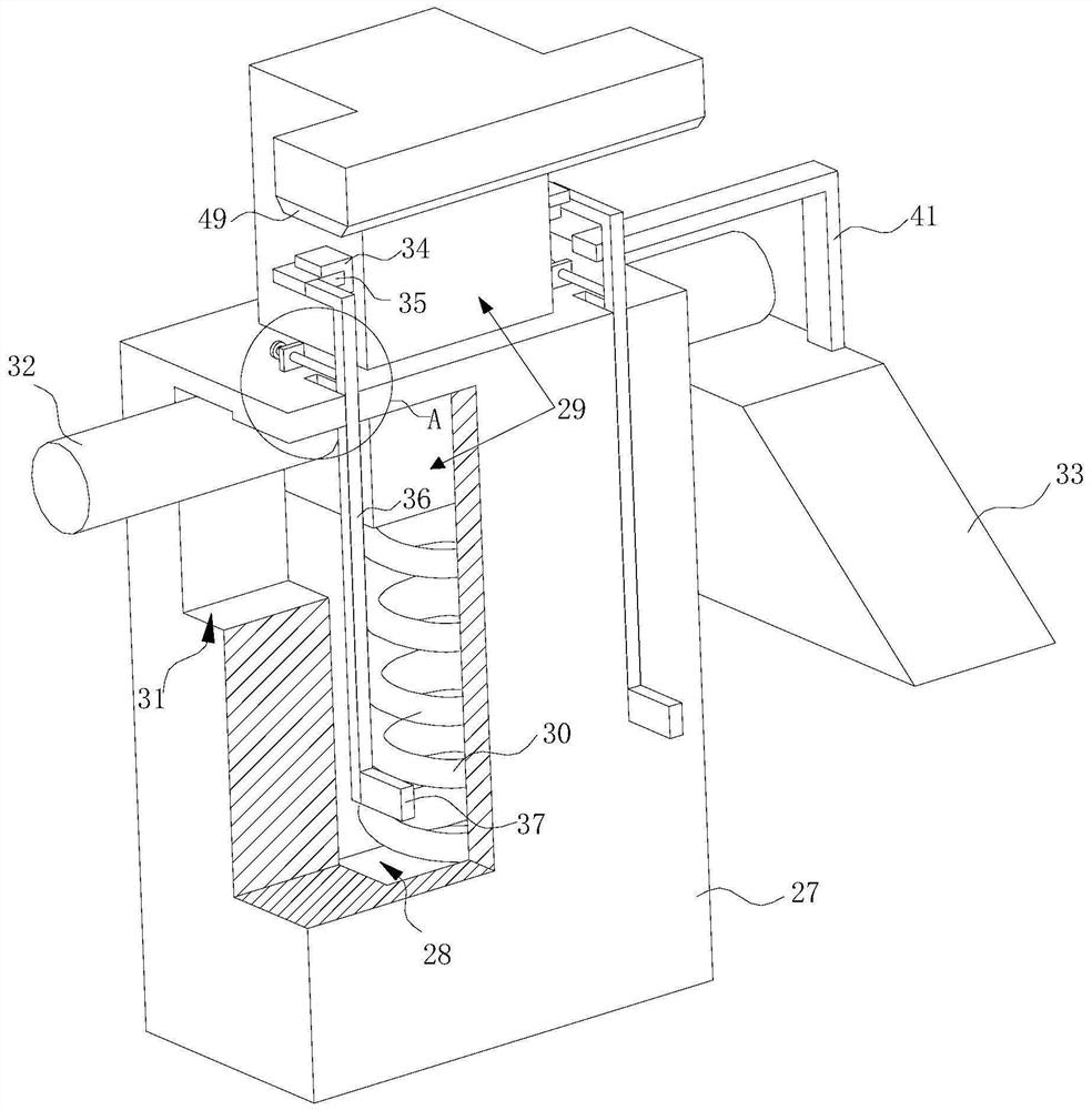
[0028] see Figure 1-6 , the present invention provides a technical solution: a stamping device for automatically correcting stamped workpieces, including a stamping mechanism and an automatic calibration mechanism, the automatic calibration mechanism is arranged in the middle of the stamping mechanism, and the stamping mechanism includes a base 1, two sides on the top of the base 1 Both sides are fixedly connected with support columns 2, the tops of the two suppor...


PUM


Abstract

The invention discloses a stamping device capable of automatically correcting and stamping workpieces in the technical field of stamping devices. The stamping device comprises a stamping mechanism andan automatic calibration mechanism, the automatic calibration mechanism is arranged at the middle position of the stamping mechanism, the stamping mechanism comprises a base, supporting stand columnsare fixedly connected to the left and right sides of the top of the base, the tops of the two supporting stand columns are jointly and fixedly connected with a supporting plate, and a hydraulic cylinder is fixedly connected to the middle position of the bottom of the supporting plate. When the hydraulic cylinder descends and before stamping is carried out, push blocks on the periphery are automatically driven to to accurately position a plate at the stamping position, then the hydraulic cylinder continues to descend to stamp the plate again, and therefore accurate positioning of the stampingcenter position of the plate is achieved, the plate machining precision is greatly improved, and the plate stamping percent of pass is greatly increased.

Description

technical field [0001] The invention relates to the field of punching devices, in particular to a punching device for automatically correcting punched workpieces. Background technique [0002] In the sheet metal parts production and processing industry, it is often necessary to perform stamping processing on sheet metal parts. Stamping processing is the power of conventional or special stamping equipment, so that the sheet metal is directly subjected to deformation force and deformed in the mold, so as to obtain a certain shape, The production technology of product parts in terms of size and performance. Compared with castings and forgings, stamping parts have the characteristics of thinness, uniformity, lightness and strength. Due to the use of precision molds, the precision of the workpiece can reach micron level, and the repeatability is high and the specifications are consistent. It can punch out certain shapes such as holes and bosses. [0003] The invention patent app...

Claims


Application Information

Patent Timeline
Patent Type & Authority Applications(China)
IPC IPC(8): B21D43/00B21D22/02
CPCB21D22/02B21D43/003
Inventor 樊晓敏程渺渺
Owner 吉安持凡电子科技有限公司
Learn More