
Machining grinding device with scrap collecting function

A mechanical processing and functional technology, applied in the device of fixing the grinding wheel, grinding/polishing safety device, metal processing equipment, etc., can solve the problems of poor safety, limited workpiece grinding, affecting the operating environment, etc. Beneficial for absorption and stable connection

Inactive Publication Date: 2021-01-22
杭州优图工业设计有限公司
View PDF0 Cites 0 Cited by
  • Summary
  • Abstract
  • Description
  • Claims
  • Application Information

AI Technical Summary

Problems solved by technology

[0004] The object of the present invention is to provide a grinding device for machining with waste collection function, so as to solve the problem that the grinding wheel cannot move flexibly during the use of the grinding device for machining proposed in the above-mentioned background technology, and the grinding of workpieces is limited, and the operation There are no protective measures in the process, the safety is poor, and the waste generated during the grinding process is splashed everywhere, which affects the operating environment and brings troublesome problems to people's use.

Method used


Image

  • Machining grinding device with scrap collecting function
  • Machining grinding device with scrap collecting function
  • Machining grinding device with scrap collecting function

Examples


Embodiment Construction

[0020] The following will clearly and completely describe the technical solutions in the embodiments of the present invention with reference to the accompanying drawings in the embodiments of the present invention. Obviously, the described embodiments are only some, not all, embodiments of the present invention. Based on the embodiments of the present invention, all other embodiments obtained by persons of ordinary skill in the art without making creative efforts belong to the protection scope of the present invention.

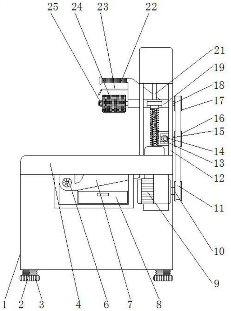
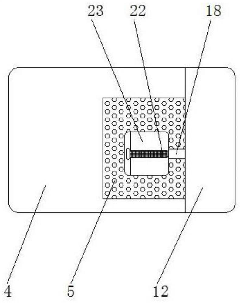
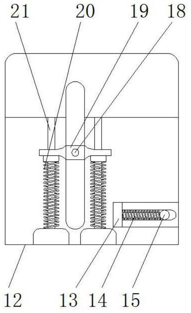
[0021] see Figure 1-3 , the present invention provides a technical solution: a grinding device for mechanical processing with a waste collection function, including a base 1 and a support frame 12, the bottom of the base 1 is provided with a threaded head 2, and the lower end of the threaded head 2 is connected with a foot Pad 3, console 4 is placed on the upper end of base 1, and collection hole 5 is opened on the right part of console 4, fan 6 is installed ...


PUM


Abstract

The invention discloses a machining grinding device with a scrap collecting function. The machining grinding device comprises a base and a supporting frame. An operation table is arranged at the upperend of the base, and a collecting hole is formed in the right portion of the operation table. A fan is installed on the left side of the bottom of the operation table, and the right side of the fan is connected with an air guide pipe. A collecting box is arranged at the lower end of the air guide pipe. The supporting frame is arranged on the upper portion of the operation table, and a tensioningwheel movable frame is arranged at the lower end of the rear portion of the supporting frame. A movable spring is arranged on the inner side of the tensioning wheel movable frame, and the rear end ofthe movable spring is connected with a tensioning wheel connecting rod. A tensioning wheel is arranged at the right end of the tensioning wheel connecting rod. A driven disc is arranged at the upper end of the front portion of the supporting frame, and a rotating shaft is arranged on the left side of the driven disc. A connecting frame is connected to the outer side of the rotating shaft, and a reset spring is arranged at the lower end of the connecting frame. The machining grinding device with the scrap collecting function is provided with the fan and the collecting box, and scraps generatedafter grinding can be collected conveniently.

Description

technical field [0001] The invention relates to the technical field of mechanical processing instruments, in particular to a grinding device for mechanical processing with the function of collecting waste. Background technique [0002] In the process of mechanical processing, it is often necessary to grind the workpiece to remove the burrs on the surface of the workpiece, which is beneficial to the subsequent processing of the workpiece. However, in the process of grinding the workpiece, it is easy to produce grinding iron chips. Therefore, Concentrated treatment of iron filings after grinding is required to avoid impact on the environment of the working area. [0003] The grinding wheel for mechanical processing on the market cannot move flexibly during use, and the grinding of the workpiece is limited, and there are no protective measures during the operation, which is poor in safety, and the waste generated during the grinding process is splashed everywhere, affecting the...

Claims


Application Information

Patent Timeline
Patent Type & Authority Applications(China)
IPC IPC(8): B24B55/06B24B27/00B24B41/02B24B41/06B24B27/02B24B45/00
CPCB24B27/0015B24B27/02B24B41/02B24B41/06B24B45/006B24B55/06
Inventor 虞春阳
Owner 杭州优图工业设计有限公司
Learn More