
Manufacturing process of directional reflective film

A production process and reflective film technology, which is applied to flat products, optical components, household appliances, etc., can solve the problems such as the failure to effectively control the temperature change of the production process and the failure to maintain the surface accuracy level of the microprism structure, so as to reduce the process consumption. time, the effect of enhancing heat dissipation

Inactive Publication Date: 2021-01-22
YESHILI NEW MATERIALS (XIANJU) CO LTD
View PDF29 Cites 1 Cited by
  • Summary
  • Abstract
  • Description
  • Claims
  • Application Information

AI Technical Summary

Problems solved by technology

The invention has a simple production process and high production efficiency, and the product has the characteristics of high adhesive performance, high weather resistance, high reflective brightness, etc., and has a long service life and a wide range of applications; The precision level of the surface of the microprism structure formed by the combination of flakes, and the problem that the temperature change in the manufacturing process cannot be effectively controlled

Method used


Image

  • Manufacturing process of directional reflective film
  • Manufacturing process of directional reflective film
  • Manufacturing process of directional reflective film

Examples


Embodiment approach

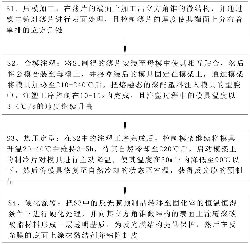
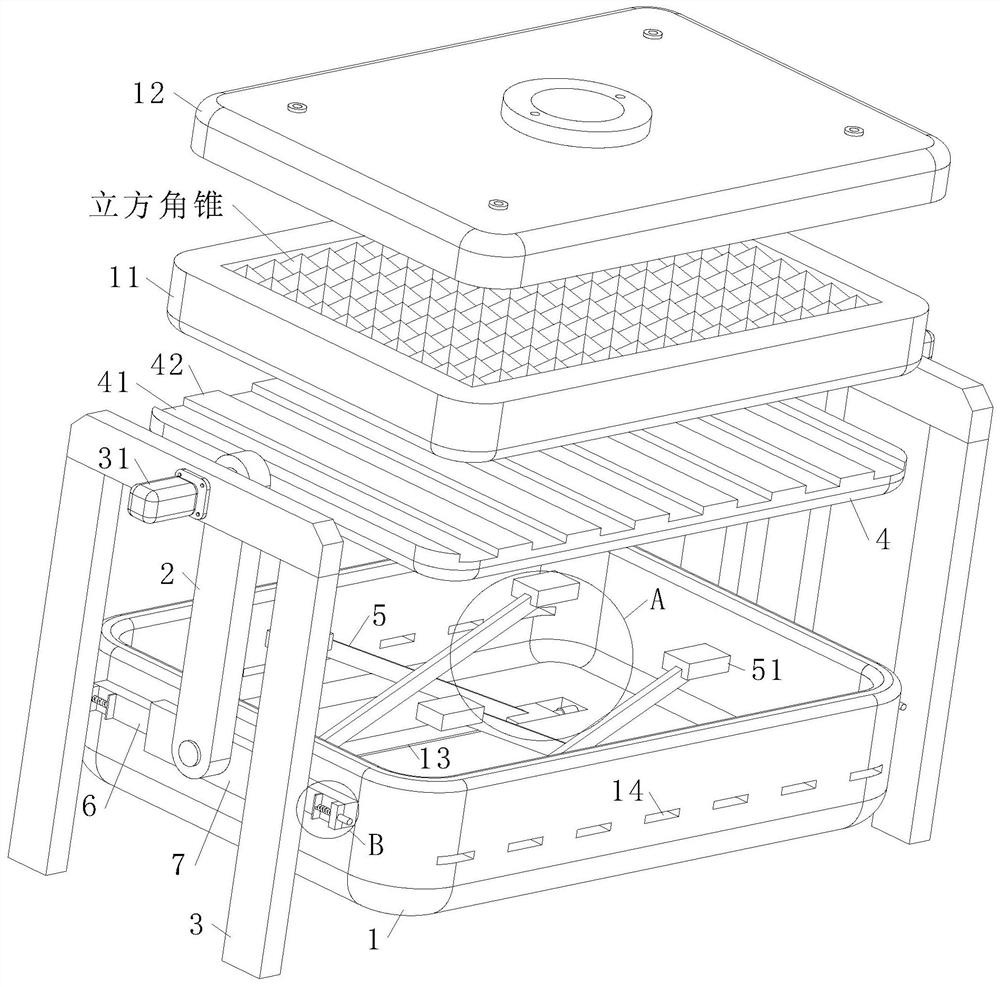
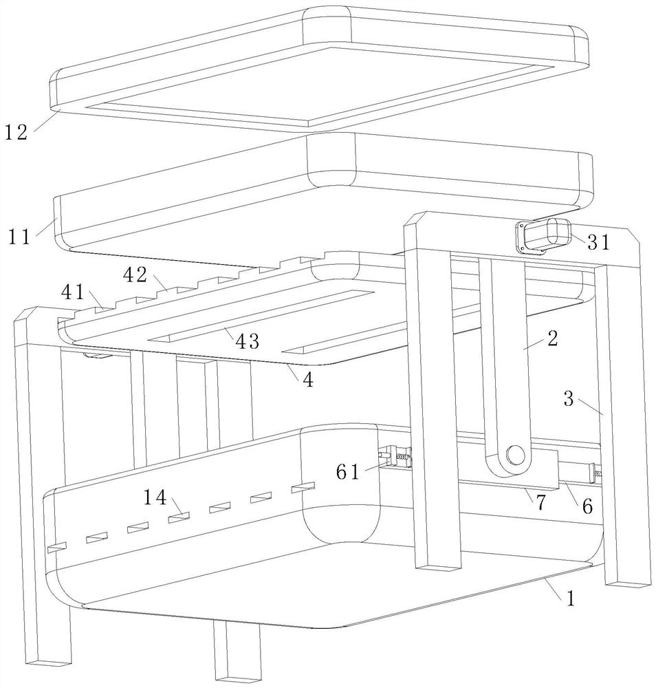
[0035] As an embodiment of the present invention, the bottom of the support shell 1 is provided with a shallow groove 13; the bottom of the supporting plate 4 is provided with a slot 43, and the slot 43 corresponds to the position of the shallow slot 13; the telescopic The end of frame 5 is provided with hinged slide block 51, and slide block 51 is respectively installed in shallow groove 13 and embedded groove 43; Also be provided with the oil cylinder 52 that drives between described slide block 51 and the end of shallow groove 13; The telescopic frame 5 in the shell 1 is used to drive the lifting of the supporting plate 4. It is necessary to control the mutual contact state between the supporting plate 4 and the bottom of the supporting shell 1 to ensure that the vibration of the supporting shell 1 is completely transmitted to the supporting plate 4. In the mold, and reduce the volume required for the support shell 1 to wrap the mold; through the shallow groove 13 and the sl...


PUM


Abstract

The invention relates to the technical field of reflective materials, in particular to a manufacturing process of a directional reflective film. The manufacturing process of the directional reflectivefilm comprises the steps of mold pressing processing, mold closing injection molding, hot-pressing shaping and hardening coating, and a mold frame adopted by the manufacturing process of the directional reflective film comprises a supporting shell, a swing rod and a controller. Due to the mutual contact state between cubic pyramid surfaces formed by combining the thin sheets, the precision of thecubic pyramid surfaces is influenced, the temperature change of a mold in the injection molding process needs to be accurately controlled, and otherwise, the quality of the reflective film formed through injection molding can be reduced. Therefore, according to the manufacturing process of the directional reflective film, the working procedure process of the reflective film injection mold is controlled through the arranged mold frame; the supporting shell is driven to vibrate through the swing rod to balance the distribution state of polyester plastic in a mold cavity, so that the overall planeness of the cubic pyramid combined by the thin sheets is kept; by utilizing the wrapping state of the supporting shell on the mold, the temperature state is accurately controlled under the action ofa supporting plate at the bottom of the mold, so that the temperature adjusting requirement in the reflective film manufacturing process is met; and therefore, the operation effect of the manufacturing process of the directional reflective film is improved.

Description

technical field [0001] The invention relates to the technical field of reflective materials, in particular to a manufacturing process of a directional reflective film. Background technique [0002] Reflective film (accurately called: retroreflective film) is a film that reflects light or radiation back to the light source, and is widely used in traffic signs and personal safety protection signs; the retroreflective units in the reflective film mainly include: There are two structures of glass microbeads and cube corners, among which the cube corner reflective film is famous for its high retroreflection efficiency, and its retroreflection coefficient for vertically incident light is 2 to 3 times higher than that of glass beads, making the cube corner reflective The development and application of the retroreflective film have been paid more attention by people; for the introduction of the manufacturing process of the retroreflective film, please refer to: Luo Han et al., Optim...

Claims


Application Information

Patent Timeline
Patent Type & Authority Applications(China)
IPC IPC(8): B29C45/14B29C45/26B29C45/56B29C45/73B29C45/00B29K67/00B29L7/00B29L11/00
CPCB29C45/14B29C45/2602B29C45/568B29C45/73B29C45/0001B29C45/0053B29C2045/14868B29C2045/0079B29K2067/00B29L2011/0083B29L2007/00
Inventor 徐君东章明能
Owner YESHILI NEW MATERIALS (XIANJU) CO LTD
Learn More