Novel charging pile power distribution system

A power distribution system and charging pile technology, applied in charging stations, electric vehicle charging technology, electric vehicles, etc., can solve the problems of unstable power supply, inability to ensure stable operation of the power grid, and sparse distribution of microgrids.

Active Publication Date: 2021-01-22
富晟新能源汽车充电技术(苏州)有限公司
View PDF6 Cites 0 Cited by
  • Summary
  • Abstract
  • Description
  • Claims
  • Application Information

AI Technical Summary

Problems solved by technology

Electric vehicles need charging piles to supplement electric energy. The charging of a small number of electric vehicles will not have a great impact on the power grid. However, due to the state's support for electric vehicles in recent years, the use of electric vehicles has greatly increased. The number of vehicles will reach 60 million. Assuming that these electric vehicles are charged at the same time, the peak power will reach 500 million kilowatts, resulting in excessive load on the power grid, especially during the peak power consumption period in summer or winter, and the stable operation of the power grid cannot be guaranteed.
[0003] With the development of my country's technology and economy and the increasing attention to energy conservation and emission reduction, the state vigorously supports the construction of micro-grids. Micro-grids are a power network that includes power generation, power distribution, and power consumption. Micro-grids mainly use photovoltaic power generation, Wind power generation is the mainstay, and the load is connected to energy storage equipment. However, due to the sparse distribution of the micro-grid and the large environmental factors, the power supply is unstable. With the rise of more and more household charging piles, the existing technology Lack of power distribution system for charging piles

Method used


Image

  • Novel charging pile power distribution system

Examples


specific Embodiment example 1

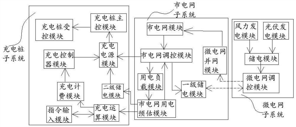
[0031] A new charging pile power distribution system, including: a charging pile system, a microgrid subsystem, and a grid subsystem; the charging pile system includes a charging pile main control module, a charging pile controlled module, a charging billing module, and a charging control module. The charger module, the charging power supply module, the charging billing module, the charging controller module, and the charging power supply module are connected in sequence, the charging power supply module is connected to the charging pile main control module, and the charging pile main control module is connected to the charging pile main control module. The charging pile is connected to the controlled module; the microgrid subsystem includes a wind power generation module, a photovoltaic power generation module, a power storage module, and a microgrid control module, and the wind power generation module and the photovoltaic power generation module are connected to the power stor...


PUM


Abstract

A novel charging pile power distribution system is characterized in that a charging pile subsystem comprises a charging pile main control module, a charging pile controlled module, a charging billingmodule, a charging controller module and a charging power supply module, and a microgrid subsystem comprises a wind power generation module, a photovoltaic power generation module, a power storage module and a microgrid regulation and control module; the commercial power grid subsystem comprises a commercial power grid module, a power utilization load module, a commercial power grid power utilization estimation module, a first-level electric quantity storage module, a commercial power grid regulation and control module and a microgrid grid connection module. Electric quantity waste of scattered micro-grids can be solved, and peak clipping and valley filling of the state grid are facilitated; the charging power of each charging pile in the region is monitored, the charging and distributionquantity is regulated and controlled according to the statistics of the mains supply power grid electricity consumption estimation module on the electricity consumption of the user, and the charging power is controlled to provide multiple charging modes for the charging user for the user to select. By controlling the change of the charging unit price, the user is encouraged to adopt full-power charging in the off-peak period of power utilization, and efficient circulation of electric energy of a mains supply network is maintained.

Description

technical field [0001] The invention relates to the technical field of electric vehicle charging, in particular to a novel charging pile power distribution system. Background technique [0002] An electric vehicle (BEV) refers to a vehicle that is powered by a vehicle-mounted power supply, drives the wheels with a motor, and meets the requirements of road traffic and safety regulations. Due to its smaller impact on the environment than traditional cars, its prospects are widely optimistic. Electric vehicles need charging piles to supplement electric energy. The charging of a small number of electric vehicles will not have a great impact on the power grid. However, due to the state's support for electric vehicles in recent years, the use of electric vehicles has greatly increased. The number of vehicles will reach 60 million. Assuming that these electric vehicles are charged at the same time, the peak power will reach 500 million kilowatts, resulting in excessive load on the...

Claims


Application Information

Patent Timeline
Patent Type & Authority Applications(China)
IPC IPC(8): B60L53/63B60L53/64B60L53/50B60L53/51
CPCB60L53/63B60L53/64B60L53/50B60L53/51Y02T10/72
Inventor 陆佳鑫
Owner 富晟新能源汽车充电技术(苏州)有限公司
Why Eureka
Try Eureka