Micro-thermal photoelectric power generation device

A power generation device, micro-thermal photoelectric technology, applied in photovoltaic power generation, photovoltaic power stations, photovoltaic modules, etc., can solve the problems of frequent charging and long charging time, and achieve high energy utilization rate, stable power supply capacity, and large utilization scenarios.

Inactive Publication Date: 2019-05-28
成都永和光学有限公司
View PDF0 Cites 0 Cited by
  • Summary
  • Abstract
  • Description
  • Claims
  • Application Information

AI Technical Summary

Problems solved by technology

Typical lightweight mechanical devices also suffer from long charging times and the need for frequent recharging

Method used


Image

  • Micro-thermal photoelectric power generation device

Examples


Embodiment Construction

[0014] In the following detailed description, numerous specific details are set forth in order to provide a thorough understanding of the present invention. It will be apparent, however, to one skilled in the art that the present invention may be practiced without some of these specific details. The following description of the embodiments is only to provide a better understanding of the present invention by showing examples of the present invention.

[0015] The technical solutions of the embodiments of the present invention will be described below with reference to the accompanying drawings.

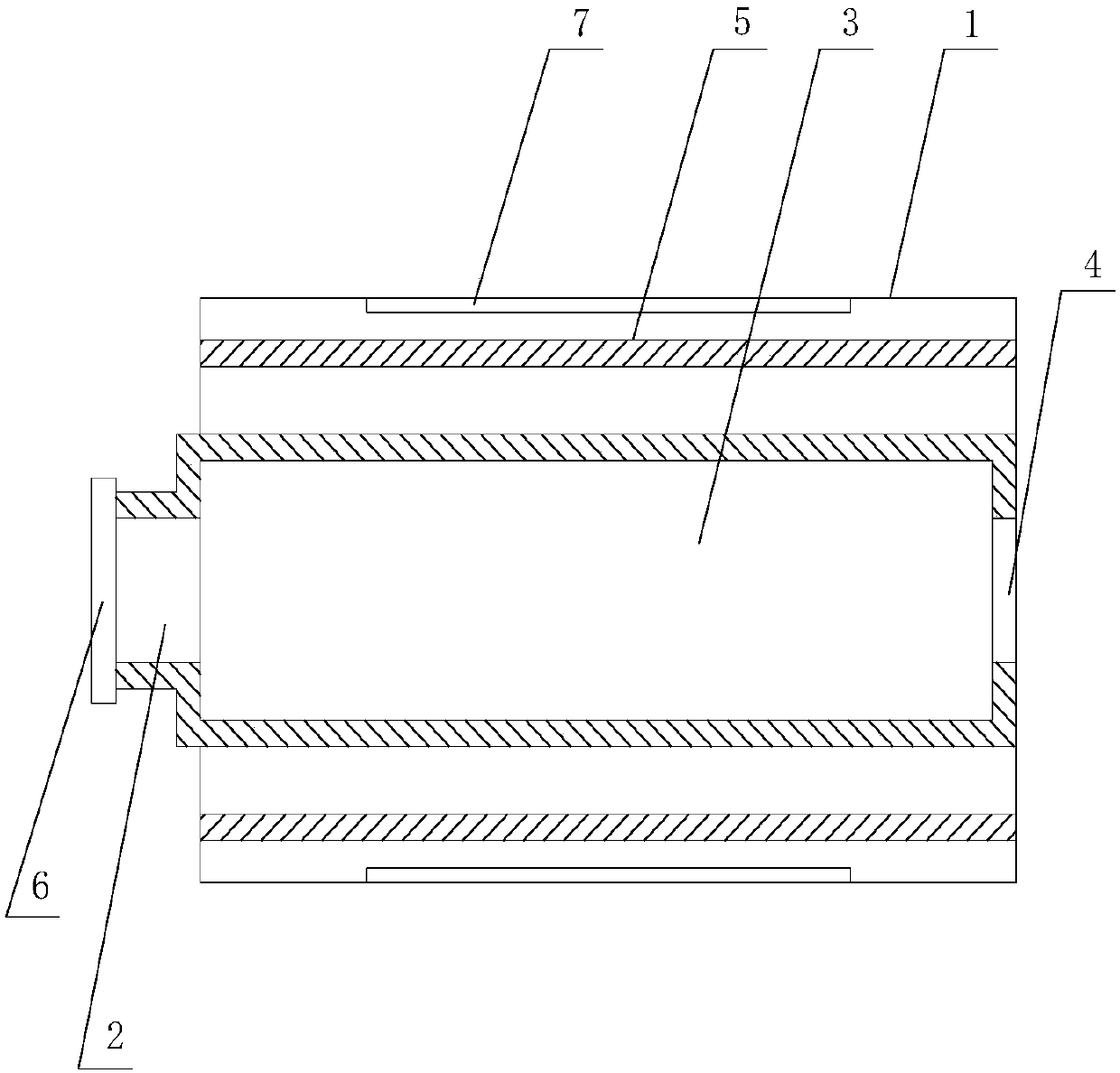
[0016] Such as figure 1 As shown, the present invention provides a microthermal photoelectric power generation device, comprising: a power generation device body 1, an air inlet 2, a combustion chamber, an exhaust port 5, and a GASB photovoltaic cell; one end of the power generation device body 1 is provided with an air inlet 2 , used for gas fuel to enter the combustion chamber 3; t...


PUM


Abstract

The invention relates to a micro-thermal photoelectric power generation device which comprises a power generation device body, an air inlet, a burning chamber, an air outlet and a photocell. The air inlet is formed in one end of the power generation device body and used for allowing gas fuel to enter the combustion chamber. The combustion chamber is arranged in the cavity of the power generation device body, and one end of the combustion chamber is connected with the air inlet for combustion of gas fuel. The photocell is arranged on the outer wall of the combustion chamber. The other end of the combustion chamber is connected with the air outlet formed in the other end of the power generation device body, and the air outlet is used for exhausting combusted waste gas. The micro-thermal photoelectric power generation device is stable in power supply capacity and high in energy utilization rate, and has a great utilization scene.

Description

technical field [0001] The invention relates to the technical field of power generation devices, in particular to a microthermal photoelectric power generation device. Background technique [0002] With the increasing trend of miniaturization of mechanical and electromechanical engineering devices, various microdevices such as micropumps, microengines, microrobots, microspacecraft and microaircraft are being developed. However, the miniaturization of these devices is limited by the available power systems (batteries). They occupy the bulk of the installation in mass and volume. Typical lightweight mechanical devices also suffer from long charging times and the need for frequent recharging. The need to reduce the weight of the system and extend the runtime has prompted the development of a new type of MEMs device, the microkinetic generator. [0003] Hydrocarbon fuels are known to be 10-100 times more energy dense than the best batteries. Therefore, harnessing the high en...

Claims


Application Information

Patent Timeline
Patent Type & Authority Applications(China)
IPC IPC(8): H02S10/30
CPCY02E10/50
Inventor 杨蔡
Owner 成都永和光学有限公司
Why Eureka
Try Eureka