
Detachable movable end wall

A movable end and detachable technology, which is applied in the field of detachable movable end walls, can solve problems such as inability to load goods, and achieve the effects of improving loading safety, low manufacturing cost, and strengthening connection stability

Pending Publication Date: 2021-01-22
CRRC MEISHAN
View PDF0 Cites 0 Cited by
  • Summary
  • Abstract
  • Description
  • Claims
  • Application Information

AI Technical Summary

Problems solved by technology

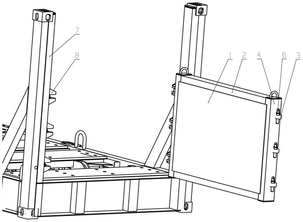
[0004] In view of the above-mentioned technical problem that the existing pallet transport end wall structure cannot load goods exceeding the length of the pallet itself, the purpose of the present invention is to provide a detachable movable end wall, which can facilitate the installation and disassembly of the end wall structure and realize The end wall rotates close to 90° on one side to meet the loading requirements of different goods

Method used


Image

  • Detachable movable end wall
  • Detachable movable end wall
  • Detachable movable end wall

Examples


Embodiment 1

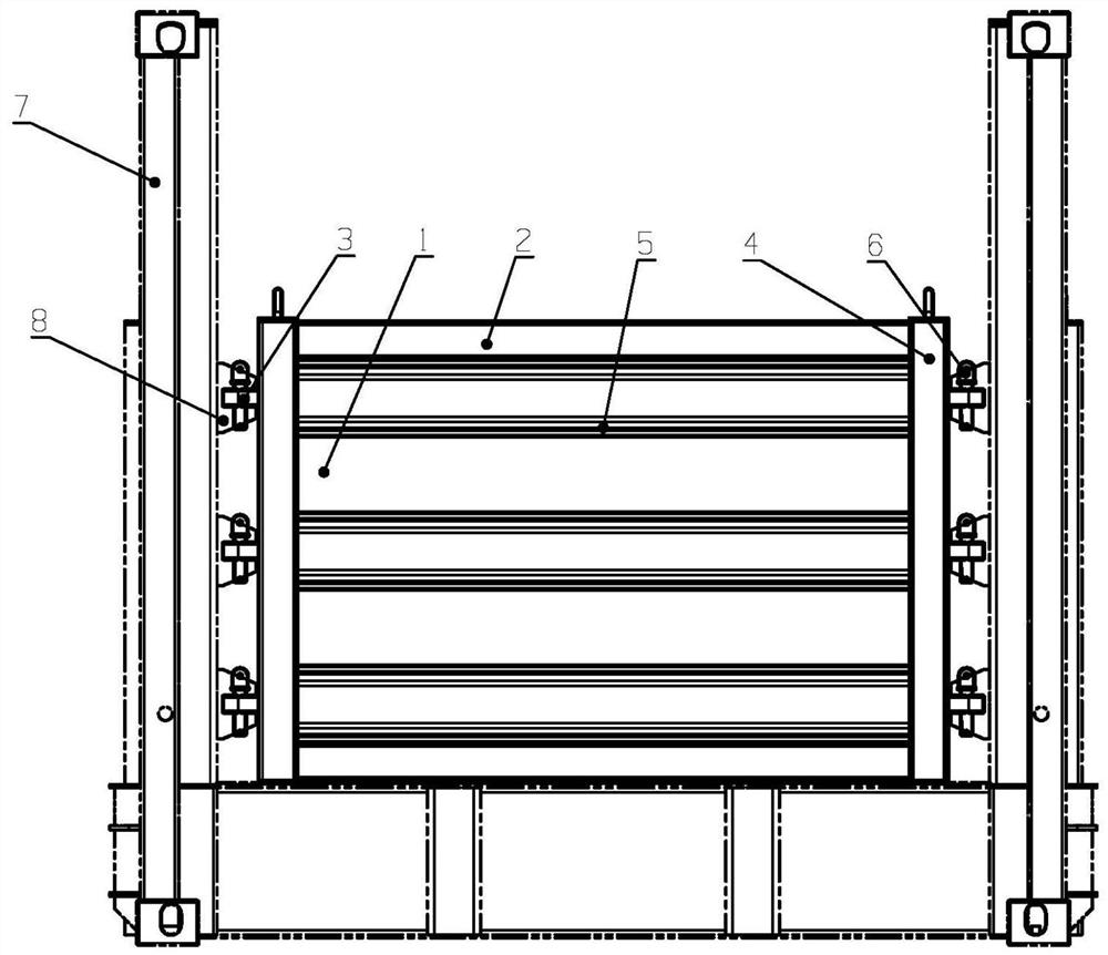
[0034] This embodiment is basically as figure 1 and figure 2 As shown: this embodiment provides a detachable movable end wall, which includes an end plate 1, an end beam 2, an end column composition 4 and a latch. The end plate 1 in this embodiment is rectangular and is located at the end of the pallet 7 part, and on the pallet 7 corresponding to both sides of the end plate 1, there are several latch seats 8; the end column composition 4 is fixed on both sides of the end plate 1, and the end column composition 4 is connected with the pallet 7 through the bolt composition The pin seat 8 on the top realizes detachable connection, and the end beam 2 is fixed on the upper and lower ends of the end plate 1, so that the end beam 2 and the end column form 4 around the end plate 1 to form a zigzag frame structure.

[0035] In this embodiment, the detachable movable end wall also includes a horizontal belt composition 5, which is fixed in the square frame structure and rigidly connec...

Embodiment 2

[0042] Embodiment 2 is basically the same as Embodiment 1, and the difference is that: as a preferred solution of Embodiment 1, in combination with figure 1 and Figure 4As shown, the present embodiment is provided with a horizontal band composition 5 rigidly connected to the end plate 1 in the square frame structure, so that the door bolt 3 passes through the end column composition 4 and the horizontal band composition 5 and is rigidly connected. The purpose of the design of the cross-belt composition 5 in the embodiment is not only to strengthen the structural strength of the end plate 1, but also to further strengthen the connection stability between the door bolt 3 and the end post composition 4. This design is ingenious and reasonable.

[0043] Specifically, the horizontal belt composition 5 includes a horizontal belt 5a corresponding to the door bolt 3 and a partition built into the inner side of the horizontal belt 5a. The partition board is provided with a mounting hol...


PUM


Abstract

The invention discloses a detachable movable end wall, and relates to the technical field of railway transportation equipment. The movable end wall comprises an end plate, end beams, end column assemblies and plug pin assemblies, wherein the end plate is arranged at the end part of a container frame, and a plurality of plug pin seats are arranged on the container frame corresponding to the two sides of the end plate; the end column assemblies are fixed on the two sides of the end plate, and the end column assemblies are detachably connected with the plug pin seats through the plug pin assemblies; and the end beams are fixed at the upper end and the lower end of the end plate, so that the end beams and the end column assemblies form a square-shaped frame structure around the periphery of the end plate. According to the technical scheme, the technical problem that an existing container frame transportation end wall structure cannot load goods exceeding the length of the container frame can be effectively solved, the end wall structure can be conveniently installed and disassembled, and the end wall can rotate by nearly 90 degrees on a single side so as to meet the loading requirements of different goods; and the detachable movable end wall is integrally designed in a light weight mode, the weight of the detachable movable end wall is reduced, and the detachable movable end wall has a good application prospect in the technical field of railway transportation equipment.

Description

technical field [0001] The invention relates to the technical field of railway transportation equipment, in particular to a detachable movable end wall. Background technique [0002] With the continuous development of my country's railway industry, the way steel is transported by railway open car and flat car is gradually changing to the way of pallet transport. [0003] At present, the structure of the pallet transport end wall in my country generally adopts a fixed upper beam or a movable upper beam, and the goods can only be placed between the two beams, so it is impossible to load goods that exceed the length of the pallet itself. Contents of the invention [0004] In view of the above-mentioned technical problem that the existing pallet transport end wall structure cannot load goods exceeding the length of the pallet itself, the purpose of the present invention is to provide a detachable movable end wall, which can facilitate the installation and disassembly of the en...

Claims


Application Information

Patent Timeline
Patent Type & Authority Applications(China)
IPC IPC(8): B65D88/52B65D90/00
CPCB65D88/52B65D90/00
Inventor 薛海莲龙建国杨诗卫李军生谢林张瑞国李冬李建超韩金刚黄盼黄瑞袁亮赵寿鑫
Owner CRRC MEISHAN
Learn More