Eureka AIR delivers breakthrough ideas for toughest innovation challenges, trusted by R&D personnel around the world.

Feeding mechanism for cross-feeding directly from the vibrating plate to the linear track

A technology of linear track and feeding mechanism, which is applied in the direction of vibrating conveyors, conveyors, conveyor objects, etc., can solve the problems of slow feeding speed, instability, and complex structure, and achieve simple structure, unique design, and breakthrough The effect of limitations

Active Publication Date: 2021-05-18
深圳市标谱半导体股份有限公司
View PDF10 Cites 0 Cited by
  • Summary
  • Abstract
  • Description
  • Claims
  • Application Information

AI Technical Summary

Problems solved by technology

[0002] At present, the feeding mechanism adopts the method of longitudinal feeding (the narrow side of the material is the direction of travel of the material); in actual work, sometimes the feeding method of the workpiece is required to be horizontal feeding The wide side is the traveling direction of the material) to meet the predetermined feeding effect. In this case, in the prior art, the material is discharged vertically, and the material is rotated 90 degrees by the manipulator before the next process. Later, it is arranged into horizontal feeding. This method has the problems of complex structure, slow feeding speed and instability.

Method used


Image

  • Feeding mechanism for cross-feeding directly from the vibrating plate to the linear track
  • Feeding mechanism for cross-feeding directly from the vibrating plate to the linear track
  • Feeding mechanism for cross-feeding directly from the vibrating plate to the linear track

Examples


Embodiment Construction

[0015] In order to make the technical problems, technical solutions and advantages to be solved by the present invention clearer, the following will describe in detail with reference to the drawings and specific embodiments.

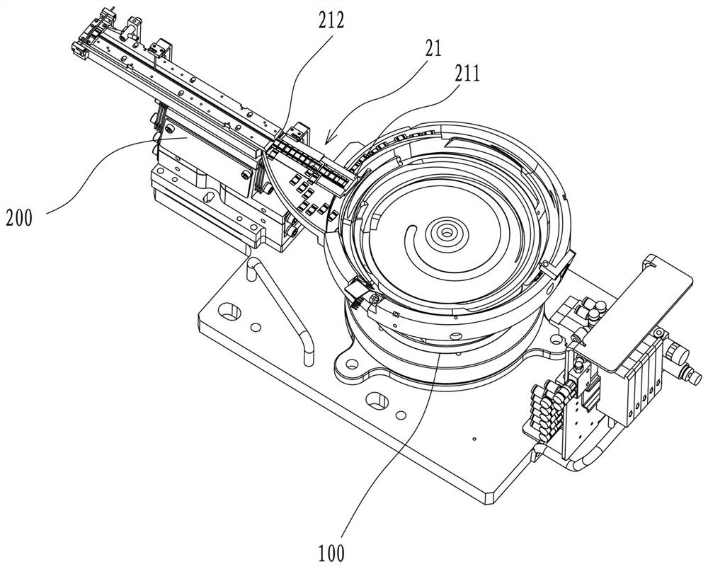
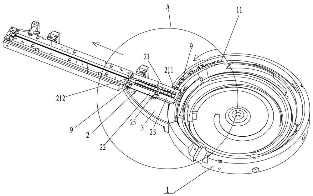
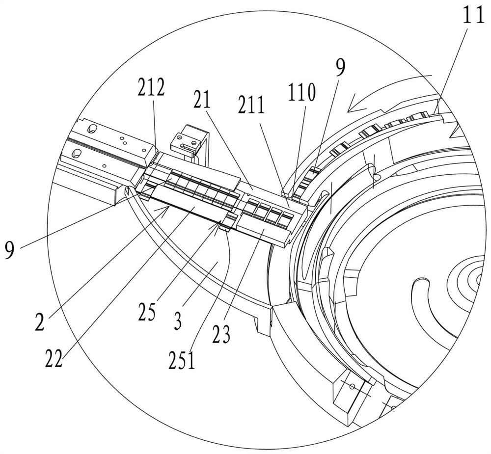
[0016] See Figure 1 to Figure 4 , Figure 1 to Figure 4 What is shown is an embodiment of a feeding mechanism that can directly realize horizontal feeding from a vibrating plate to a linear track. A feeding mechanism that can directly realize horizontal feeding from a vibrating plate to a linear track includes a feeding mechanism with The circular vibration feeding device 100 of the disk 1 and the direct vibration conveying device 200 with the direct vibration rail 2, the feeding disk 1 has the feeding rail 11 for longitudinal feeding, and the direction of the workpiece 9 on the direct vibration rail 2 The direction of the workpiece 9 at the outlet end 110 of the feeding track 11 is perpendicular to each other, and the direction of the workpiece (9) on...


PUM


Abstract

A feeding mechanism that can directly realize lateral feeding from a vibrating plate to a linear track, including a circular vibrating feeding device with a feeding pan and a direct vibrating conveying device with a direct vibrating track. The feeding pan has a vertical feeding mechanism. Material track, the direction of the workpiece on the direct vibration track and the direction of the workpiece at the outlet end of the feed track are perpendicular to each other, the direct vibration track has a direction-changing section, and the feed end of the direction-changing section is connected to the feeding The outlet end of the track is butted, and the bottom surface of the feed end of the direction changing section is a downwardly inclined slope, the length of the slope is greater than or equal to the length of the workpiece, so that the workpieces are arranged laterally on the slope, and the variable The bottom surface of the discharge end of the direction-changing section is a horizontal plane, and the track bottom surface of the direction-changing section is a twisted surface that gradually twists from an inclined plane to a horizontal plane from the feeding end to the discharging end; the bezel. The invention has the advantages of simple structure, fast feeding speed and stable feeding.

Description

technical field [0001] The invention relates to the field of feeding mechanisms, in particular to a feeding mechanism that can directly realize lateral feeding from a vibrating plate to a linear track. Background technique [0002] At present, the feeding mechanism adopts the method of longitudinal feeding (the narrow side of the material is the direction of travel of the material); in actual work, sometimes the feeding method of the workpiece is required to be horizontal feeding The wide side is the traveling direction of the material) to meet the predetermined feeding effect. In this case, in the prior art, the material is discharged vertically, and the material is rotated 90 degrees by the manipulator before the next process. Later, it is arranged into horizontal feeding, which has the problems of complex structure, slow feeding speed and instability. Contents of the invention [0003] In view of the deficiencies of the prior art, the object of the present invention is...

Claims


Application Information

Patent Timeline
Patent Type & Authority Patents(China)
IPC IPC(8): B65G27/02B65G27/16B65G47/24B65G47/26
CPCB65G27/02B65G27/16B65G47/24B65G47/26
Inventor 段雄斌杨奥博何选民
Owner 深圳市标谱半导体股份有限公司
Why Eureka
Eureka Blog
Learn More