
Integrated conveying device with rapid forming function

A transmission device and functional technology, which is applied in the field of integrated transmission devices, can solve the problems of complex and cumbersome processing equipment structures and large footprints of molding equipment, and achieve the effects of simple structure, improved molding effect, and convenient use

Active Publication Date: 2021-01-22
虎丘影像(苏州)股份有限公司
View PDF9 Cites 0 Cited by
  • Summary
  • Abstract
  • Description
  • Claims
  • Application Information

AI Technical Summary

Problems solved by technology

[0003] First of all, in the thin material transmission process, the transmission device is used to pull and unfold the rolled long thin material. However, the length of the thin material required in reality is much smaller than that of the rolled thin material. In the subsequent process, the long thin material needs to be separated. Cutting into the required specifications, in order to facilitate the subsequent accurate slitting, a transmission device is required that can pre-form traces of the marking position during the thin material transmission process for subsequent processing; secondly, the processing of thin materials is often carried out on the surface Processing, it is more common to carry out simple shape forming processing on the surface of thin materials, while large-scale forming equipment occupies a large area, and as an independent processing equipment, it is necessary to feed thin materials into it, and additional The transfer device makes the structure of the whole processing equipment complex and cumbersome

Method used

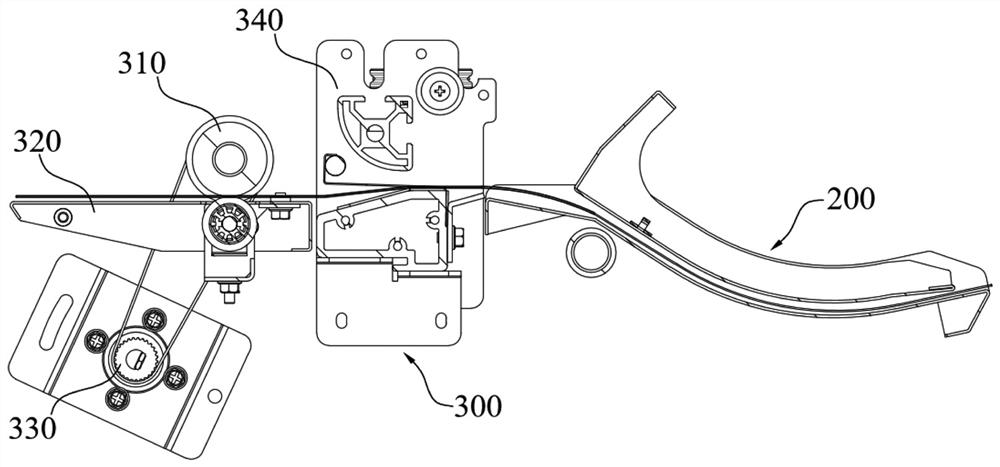
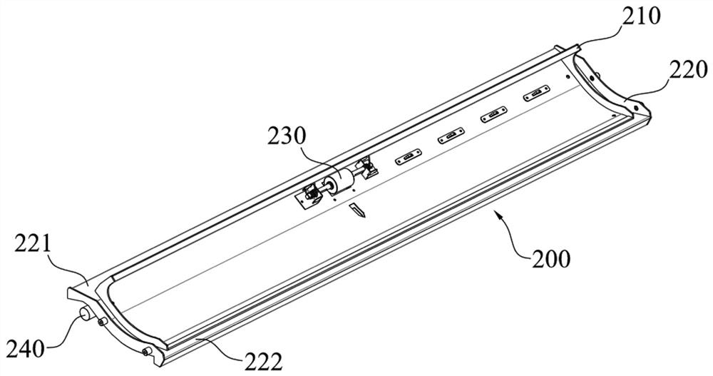
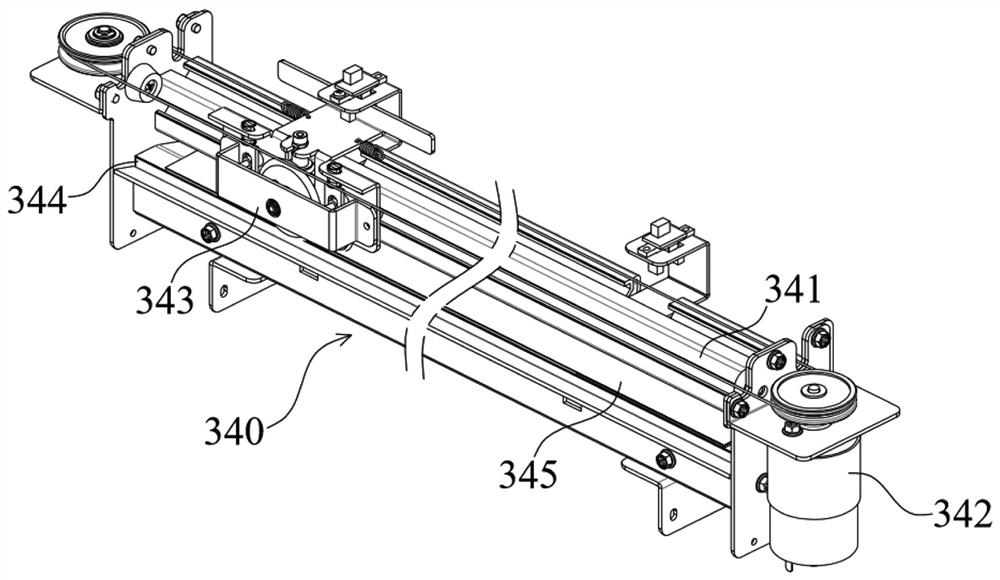

Image

  • Integrated conveying device with rapid forming function
  • Integrated conveying device with rapid forming function
  • Integrated conveying device with rapid forming function

Examples


Embodiment Construction

[0075] The present invention will be further described in detail below in conjunction with the accompanying drawings, and the aforementioned and other objects, features, aspects and advantages of the present invention will become more apparent, so that those skilled in the art can implement them with reference to the description. The described embodiment It is only a part of the embodiments of the present invention, but not all of them. Based on the implementation methods in the present invention, all other embodiments obtained by persons of ordinary skill in the art without making creative efforts belong to the protection scope of the present invention.

[0076] In the drawings, the shapes and dimensions may be exaggerated for clarity, and the same reference numerals will be used throughout to designate the same or like parts.

[0077] Unless otherwise defined, the technical terms or scientific terms used herein shall have the usual meanings understood by those skilled in the...


PUM


Abstract

The invention provides an integrated conveying device with a rapid forming function. The integrated conveying device comprises a material guide part, a functional module and a feeding channel. A pressing wheel module for driving a thin material to move is arranged on the material guide part. The functional module is used for machining the thin material conveyed from the direction of the material guide part and is arranged at the downstream end of the material guide part. The feeding channel is used for conveying the machined thin material. The functional module comprises an upper pressing partand a lower forming part, and the upper pressing part is obliquely pressed on the lower forming part. One side face of the upper pressing part abuts against the upper abutting edge of the lower forming part. The thin material is driven by the pressing wheel module to be fed into the functional module through the material guide part, passes through the abutting position of the upper pressing partand the lower forming part and then extends into the feeding channel. The functional module further comprises a driver for driving the upper pressing part, the upper pressing part is driven by the driver to be dragged on the lower forming part, and then the thin material is pressed and formed from the abutting position of the upper pressing part and the lower forming part. The integrated conveyingdevice with the rapid forming function is convenient to use and simple in structure.

Description

technical field [0001] The invention belongs to the field of feeding devices, and in particular relates to an integrated transmission device with a rapid prototyping function. Background technique [0002] In the field of feeding devices, in the process of conveying thin materials, especially in the process of conveying thin materials, the inventors have found that the existing conveying devices have at least the following problems: [0003] First of all, in the thin material transmission process, the transmission device is used to pull and unfold the rolled long thin material. However, the length of the thin material required in reality is much smaller than that of the rolled thin material. In the subsequent process, the long thin material needs to be separated. Cutting into the required specifications, in order to facilitate the subsequent accurate slitting, a transmission device is required that can pre-form traces of the marking position during the thin material transmis...

Claims


Application Information

Patent Timeline
IPC IPC(8): B65H37/00B65H5/36
CPCB65H5/36B65H37/00B65H2301/512
Inventor 宋拥军伍锡焱吴文兴
Owner 虎丘影像(苏州)股份有限公司
Learn More