Weather resistance detection instrument
A technology for testing instruments and performance, applied in the field of instruments, can solve the problems of short instrument life, inconvenient observation, inconvenient use, etc., and achieve the effects of improving anti-corrosion performance, optimizing physical and chemical properties, and reducing viscosity
- Summary
- Abstract
- Description
- Claims
- Application Information
AI Technical Summary
Problems solved by technology
Method used
Image
Examples
Embodiment 1
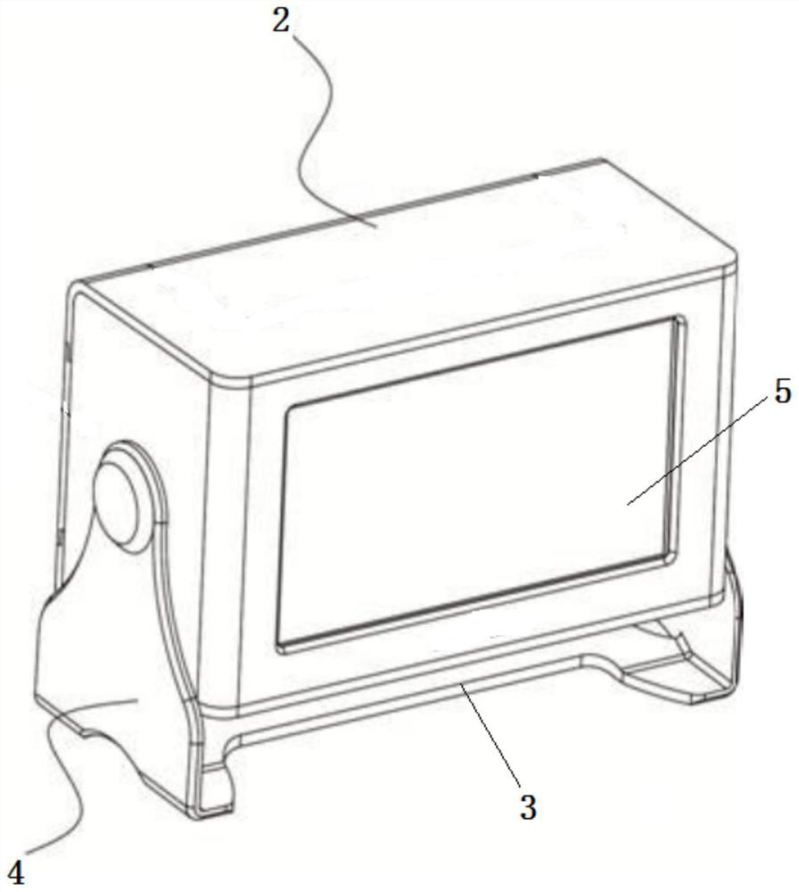
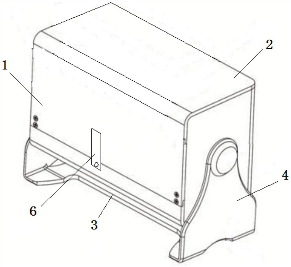
[0059] A kind of weather resistance testing instrument provided in this embodiment has a structure such as Figure 1-2 As shown, it includes the instrument main body 1 and the bracket, the bracket is arranged at the bottom of the instrument main body 1, and a protective layer is provided on the surface of the instrument main body 1, wherein:
[0060] The bracket includes a mounting groove 2, a bracket bottom plate 3, and a connecting arm 4. Both sides of the bracket bottom plate 3 are symmetrically provided with connecting arms 4, and the two connecting arms 4 are arranged on both sides of the mounting groove 2, and the instrument body 1 is arranged in the mounting groove 2. One side of the installation groove 2 is provided with a transparent observation window 5, the other side of the installation groove 2 is an opening structure, and the lower end of the installation groove 2 opening structure is provided with a fixed block 6;
[0061] The protective layer is formed by apply...
Embodiment 2
[0096] A kind of weather resistance testing instrument provided in this embodiment has a structure such as Figure 1-2 As shown, it includes the instrument main body 1 and the bracket, the bracket is arranged at the bottom of the instrument main body 1, and a protective layer is provided on the surface of the instrument main body 1, wherein:
[0097] The bracket includes a mounting groove 2, a bracket bottom plate 3 and a connecting arm 4. Both sides of the bracket bottom plate 3 are symmetrically provided with connecting arms 4, and the two connecting arms 4 are arranged on both sides of the mounting groove 2, and the instrument main body 1 is arranged in the mounting groove 2. One side of the installation groove 2 is provided with a transparent observation window 5, the other side of the installation groove 2 is an opening structure, and the lower end of the installation groove 2 opening structure is provided with a fixed block 6;
[0098] The protective layer is formed by a...
Embodiment 3
[0133] A kind of weather resistance testing instrument provided in this embodiment has a structure such as Figure 1-2 As shown, it includes the instrument main body 1 and the bracket, the bracket is arranged at the bottom of the instrument main body 1, and a protective layer is provided on the surface of the instrument main body 1, wherein:
[0134] The bracket includes a mounting groove 2, a bracket bottom plate 3 and a connecting arm 4. Both sides of the bracket bottom plate 3 are symmetrically provided with connecting arms 4, and the two connecting arms 4 are arranged on both sides of the mounting groove 2, and the instrument main body 1 is arranged in the mounting groove 2. One side of the installation groove 2 is provided with a transparent observation window 5, the other side of the installation groove 2 is an opening structure, and the lower end of the installation groove 2 opening structure is provided with a fixed block 6;
[0135] The protective layer is formed by a...
PUM
 Abstract
Description
Claims
Application Information
 - R&D
- Intellectual Property
- Life Sciences
- Materials
- Tech Scout
- Unparalleled Data Quality
- Higher Quality Content
- 60% Fewer Hallucinations
Browse by: Latest US Patents, China's latest patents, Technical Efficacy Thesaurus, Application Domain, Technology Topic, Popular Technical Reports.
© 2025 PatSnap. All rights reserved.Legal|Privacy policy|Modern Slavery Act Transparency Statement|Sitemap|About US| Contact US: help@patsnap.com


