Portable frame special for urban planning and design

A technology of urban planning and design and special racks, which is applied in the direction of mechanical equipment, machines/supports, cleaning methods and utensils, etc., to achieve the effect of ensuring stability

Active Publication Date: 2021-01-22
TONGREN POLYTECHNIC COLLEGE
View PDF8 Cites 2 Cited by
  • Summary
  • Abstract
  • Description
  • Claims
  • Application Information

AI Technical Summary

Problems solved by technology

[0004] Aiming at the deficiencies in the prior art, the purpose of the present invention is to provide a portable special rack for urban planning and design to solve the existing problems

Method used


Image

  • Portable frame special for urban planning and design
  • Portable frame special for urban planning and design
  • Portable frame special for urban planning and design

Examples


no. 1 example

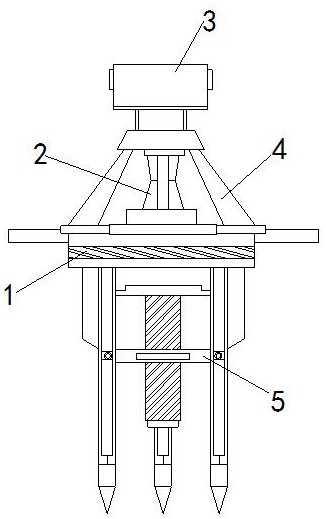
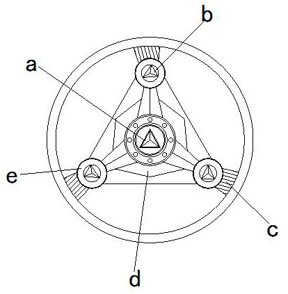
[0025] see Figure 1-Figure 3 , the present invention provides a technical solution for a portable special frame for urban planning and design: its structure includes: a tripod plate device 1, a power device 2, an instrument fixing frame 3, a connecting rod device 4, and a binding strip 5, and the instrument fixing frame 3 is installed Above the connecting rod device 4 and locked with the connecting rod device 4, a power device 2 is provided on the middle side of the connecting rod device 4, and the power device 2 is fastened with the connecting rod device 4, and a power device 2 is arranged below the connecting rod device 4 There is a tripod plate device 1, the tripod plate device 1 is fastened with the connecting rod device 4, and the side of the tripod plate device 1 is provided with a binding strip 5, and the binding strip 5 is fastened with the tripod plate device 1 , the tripod plate device 1 includes a movable rod device a, a supporting foot rod b, a chute assembly plat...

no. 2 example

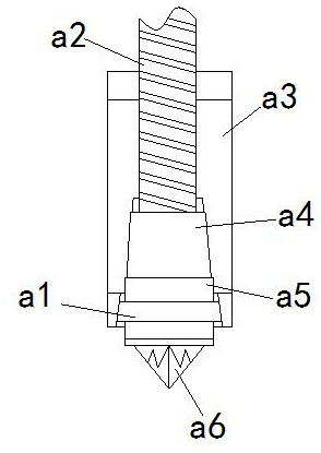
[0029] see Figure 4-Figure 5 , the present invention provides a technical solution for a portable special frame for urban planning and design: its structure includes: the scraper device a1 includes a soil-separating device a11, a stress block a12, and an outer casing a13, and the soil-separating device a11 is installed on the stress The inner side of the block a12 is locked with the stress block a12, and the outside of the stress block a12 is provided with an outer frame a13, and the outer frame a13 is buckled with the stress block a12.

[0030] The soil barrier device a11 includes a scraper a111, a fixing groove a112, and a spring piece a113. The scraper a111 is installed inside the fixing groove a112 and is fastened with the fixing groove a112. A spring piece a113 is arranged under the scraper a111 , the spring piece a113 is in clearance fit with the scraper a111, and the soil spacer device a11 can fix the direction of the scraper a111 through the cooperation of the spring ...


PUM


Abstract

The invention discloses a portable frame special for urban planning and design. The portable frame structurally comprises a foot stand disc device, a power device, an instrument fixing frame, a connecting rod device and a binding strip, wherein the instrument fixing frame is installed above the connecting rod device and connected with the connecting rod device in a locked mode. When the equipmentis used, through the arranged foot stand disc mechanism, the problem that in the surveying and mapping work development process, the accuracy of surveying and mapping data is directly affected due tothe fact that a traditional fixing mode is prone to sliding in the harsh geographical environment, especially in the slippery soil environment, and consequently equipment shakes can be solved. According to the equipment, through mutual cooperation of a movable rod device and supporting foot rods, three-point supporting is adopted to be matched with a stabilizing rod structure with the middle penetrating into a soil layer, then the stability of the surveying and mapping process can be guaranteed, meanwhile, the carried soil layer can be automatically separated through a scraping cylinder devicewhen the equipment is folded, and more convenience is achieved.

Description

technical field [0001] The invention is a portable special rack for urban planning and design, which belongs to the field of design racks. Background technique [0002] With the development of social economy, the emergence of cities, and the complexity of human living environment, the idea of ​​urban planning and design has been produced and has been continuously developed. In urban planning and design, it is often necessary to collect and investigate some basic data to study and meet the goals of urban development. Before urban planning and design, taking real photos on the spot and understanding the natural environmental conditions of the city in detail is the basic work. [0003] The existing technology has the following disadvantages: in the process of some surveying and mapping work, it is faced with a relatively harsh geographical environment, especially in a relatively slippery soil environment, the traditional fixing method is easy to cause slippage, causing the equi...

Claims


Application Information

Patent Timeline
IPC IPC(8): F16M11/04F16M11/24B08B1/00B08B1/02G01C15/00
CPCF16M11/04F16M11/247G01C15/00B08B1/165B08B1/20
Inventor 马雪石勇美高小飞
Owner TONGREN POLYTECHNIC COLLEGE
Why Eureka
Try Eureka