Supercharge Your Innovation With Domain-Expert AI Agents!

Induction heating assembly of floor heating heater

An induction heating and heater technology, applied in water heaters, fluid heaters, heating methods, etc., can solve the problem of uneven heating of water flow, achieve the effect of uniform heating of water flow and improve heating efficiency

Inactive Publication Date: 2021-01-22
安徽佳暖节能科技有限公司
View PDF8 Cites 0 Cited by
  • Summary
  • Abstract
  • Description
  • Claims
  • Application Information

AI Technical Summary

Problems solved by technology

[0006] The purpose of the present invention is to provide an induction heating assembly for a floor heating heater. By setting a heating column in the heating tube, the center of the water flow can be separated and flow closer to the wall of the heating tube, which improves the uniformity of heating and solves the problem of uneven heating of the existing water flow. The problem

Method used


Image

  • Induction heating assembly of floor heating heater
  • Induction heating assembly of floor heating heater
  • Induction heating assembly of floor heating heater

Examples


Embodiment 1

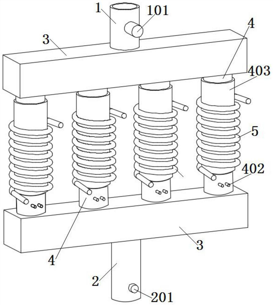
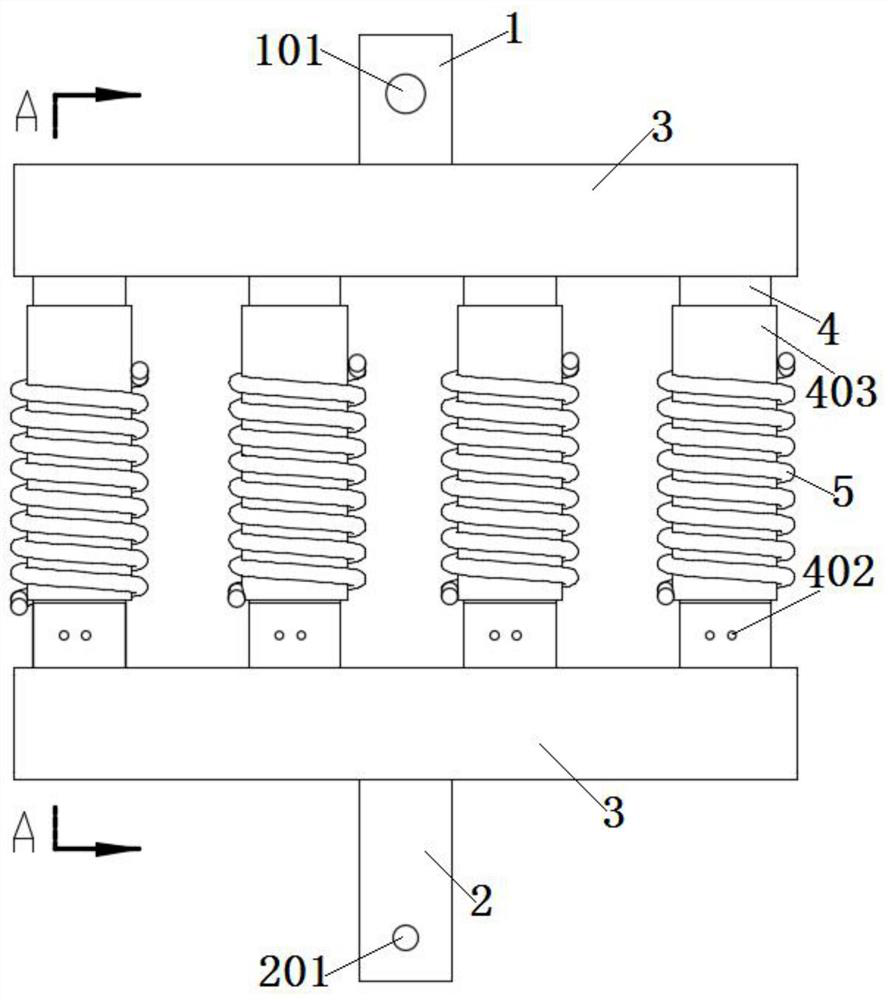
[0034]Seefigure 1 with2As shown, the present invention is an induction heating component of a floor heating heater, including a water inlet pipe 1 and a water outlet pipe 2; both the water inlet pipe 1 and the water outlet pipe 2 are connected with rectangular pipes 3 with closed ends; the water inlet pipe 1 is connected with a water flow sensor Switch 101; the outlet pipe 2 is connected with a first temperature sensor 201.

[0035]Four heating tubes 4 are connected in parallel between the two rectangular tubes 3, and the water inlet tube 1, the water outlet tube 2, the rectangular tube 3 and the heating tube 4 are all connected to each other. Both ends of the heating tube 4 are connected to the rectangular tube 3 through flanges, so that the heating tube 4 is easy to disassemble and install. The heating tube 4 can also be directly connected to the rectangular tube 3 by welding.

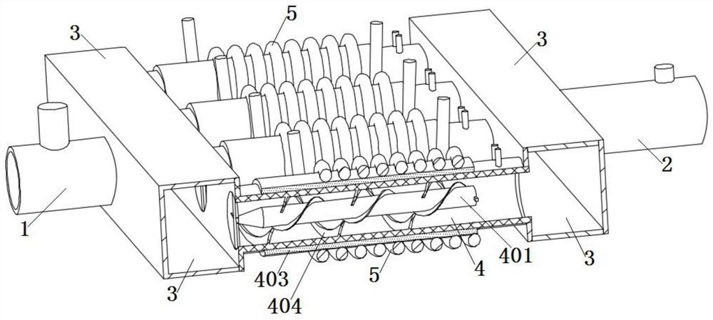
[0036]The heating tube 4 is sleeved with an electromagnetic induction coil 5; the electromagnetic induction c...

Embodiment 2

[0044]Such asfigure 1 with2As shown, both the water inlet pipe 1 and the water outlet pipe 2 are connected with a rectangular pipe 3 with closed ends. The water inlet pipe 1 and the water outlet pipe 2 and the rectangular pipe 3 can be connected by flange connection or direct welding connection. The water inlet pipe 1 is connected with a water flow sensor switch 101; the water outlet pipe 2 is connected with a first temperature sensor 201.

[0045]Four heating tubes 4 are connected in parallel between the two rectangular tubes 3, and the water inlet tube 1, the water outlet tube 2, the rectangular tube 3 and the heating tube 4 are all connected to each other. Both ends of the heating tube 4 are connected to the rectangular tube 3 through flanges, so that the heating tube 4 is easy to disassemble and install.

[0046]The heating tube 4 is sleeved with an electromagnetic induction coil 5; the electromagnetic induction coil 5 is connected with the control circuit. The inner wall of the heati...


PUM


Abstract

The invention discloses an induction heating assembly of a floor heating heater, and relates to the technical field of floor heating. The induction heating assembly comprises a water inlet pipe and awater outlet pipe. The water inlet pipe and the water outlet pipe are each connected with a rectangular pipe with two closed ends. The water inlet pipe is connected with a water flow induction switch.The water outlet pipe is connected with a first temperature sensor. A plurality of heating pipes are connected in parallel between the two rectangular pipes. The heating pipes are sleeved with an electromagnetic induction coil. Heating columns are fixedly connected to the inner walls of the heating pipes. The heating pipes are connected with a second temperature sensor. The end, facing the waterinlet pipe, of each heating column is of a circular-truncated-cone-shaped structure. The heating columns are in clearance fit with the heating pipes. The heating columns are arranged in the heating pipes, so that water flow in each heating pipe is separated at the center, the water flow uniformly flows close to the wall of each heating pipe, the water flow is heated more uniformly under the actionof the heating pipes with the electromagnetic induction coil, and the heating efficiency of the heating pipes is greatly improved.

Description

Technical field[0001]The invention belongs to the technical field of floor heating, and particularly relates to an induction heating component of a floor heating heater.Background technique[0002]With the advancement of society, people's pursuit of quality of life is also increasing. The characteristics of water floor heating due to low installation and use costs, large heating area, and long heating time have been widely used in recent years.[0003]The conventional method is usually to place the heating body in the water body to heat the water body. Although the heating effect can be achieved, there are also problems such as low heat exchange efficiency and uneven water temperature increase.[0004]The existing water floor heating usually uses electromagnetic heating, that is, the principle of electromagnetic induction to complete the heating of water. The principle: the high-speed changing alternating current will produce a high-speed changing alternating magnetic field when passing t...

Claims


Application Information

Patent Timeline
IPC IPC(8): F24H1/14F24H9/00F24H9/14F24H9/18F24H9/20F24D13/04
CPCF24D13/04F24H1/142F24H9/0005F24H9/14F24H9/1818F24H9/2028F24H2250/08
Inventor 马志凯马祥龙郭忠杰
Owner 安徽佳暖节能科技有限公司
Features
  • R&D
  • Intellectual Property
  • Life Sciences
  • Materials
  • Tech Scout
  • Unparalleled Data Quality
  • Higher Quality Content
  • 60% Fewer Hallucinations
Learn More