Shielding structure and shielding system for dismounting reactor detector assembly and using method
A detector assembly and shielding structure technology, which is applied in the direction of reactor fuel elements, reactors, and greenhouse gas reduction, can solve the problem of no patent application for detector assembly shielding structure, and achieve the effect of small weight, high work efficiency, and exquisite structure
- Summary
- Abstract
- Description
- Claims
- Application Information
AI Technical Summary
Problems solved by technology
Method used
Image

Examples
Embodiment 1
[0052] Such as figure 1 , figure 2 as shown,
[0053] The direction on which the present invention is based is described as follows:
[0054] Take looking down on a flat paper as an example,
[0055] Left, left, and left ends are located on the left of a sheet of paper; right, right, and right ends are located on the right of a sheet of paper; upper, upper, and upper ends are located above a sheet of paper; Located on the left side of a piece of paper, the front, front side, and front end are located in front of a piece of paper (facing the direction of the paper), and the back, rear side, and rear end are located behind a piece of paper (facing away from the paper) direction).
[0056] Such as figure 1 , figure 2 Schematic side view of the shielding structure for removal of the reactor detector assembly.
[0057] The subsequent front and back refer to the direction facing the legend paper and the direction facing away from the paper as shown in the figure.
[0058] ...
Embodiment 2
[0082] Such as figure 1 , figure 2 Shown:
[0083] Shielding system, including:
[0084] Based on the shielding structure for removal of the reactor detector assembly;
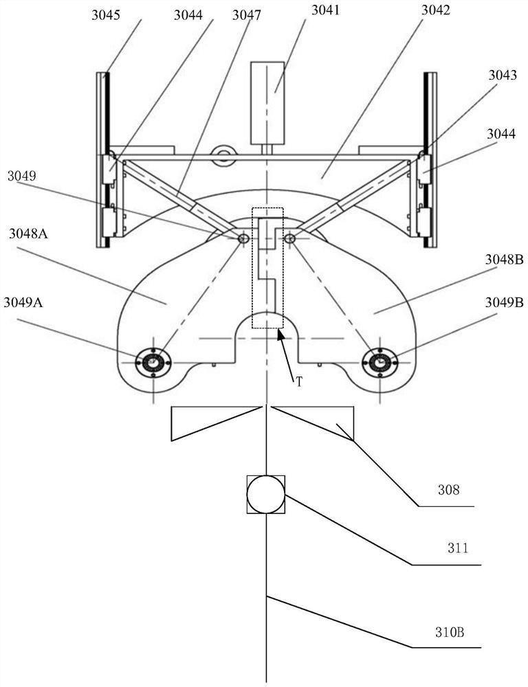
[0085] The shearing cutter 308 located under the left shield 3048A and the right shield 3048B;
[0086] a winding shaft 311 located below the shearing knife 308;
[0087] The detector assembly gripper that pulls the detector assembly from bottom to top;
[0088] From bottom to top, the detector assembly passes through the winding shaft 311 , the shearing tool 308 , the left shield 3048A, and the right shield 3048B.
Embodiment 3
[0090] Such as figure 1 , figure 2 Shown:
[0091] The method of use includes the following steps:
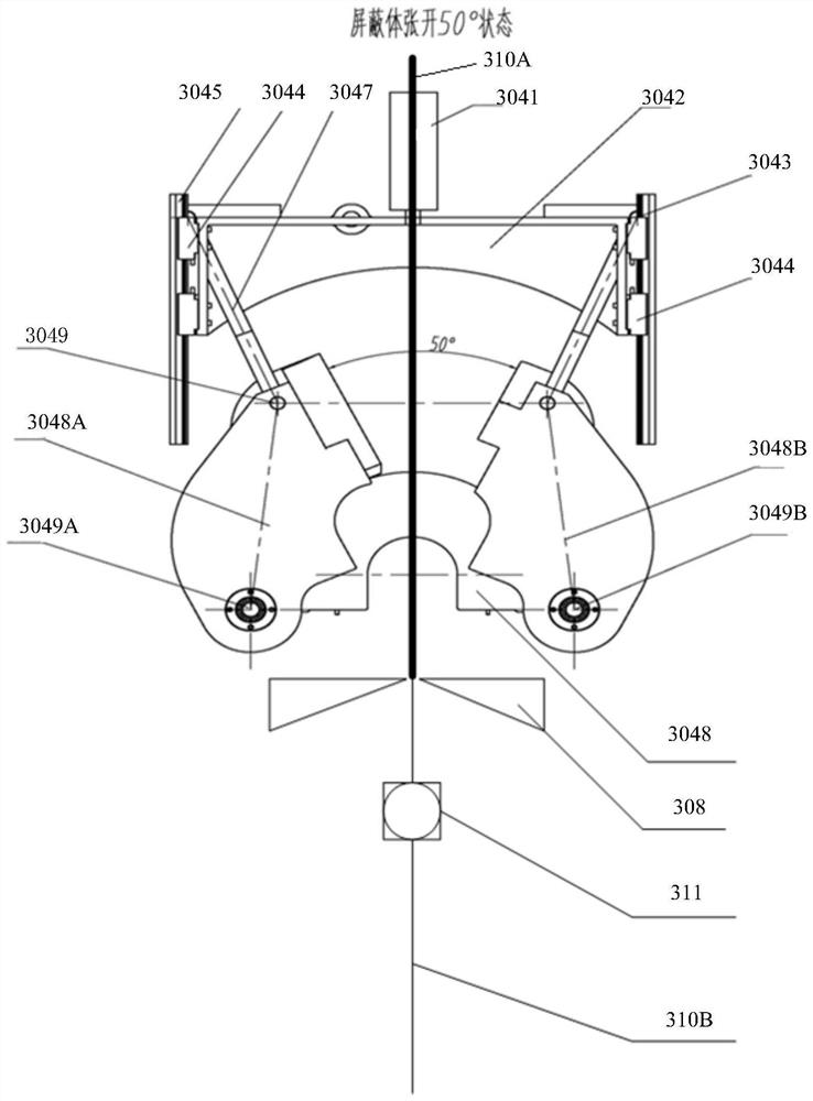
[0092]S2. Drive the driving body A or / and driving body B through the actuator, drive the left shielding body 3048A to rotate leftward around the left shielding shaft 3049A, and the right shielding body 3048B to rotate rightward around the right shielding shaft 3049B, and the left shielding body 3048A 1. The gap between the shielding body 3048B on the right side is opened;
[0093] S2. Hoist the detector assembly upwards by the detector assembly gripper, and turn to S3 after the detector assembly passes between the left shield body 3048A and the right shield body 3048B and reaches a certain height;
[0094] S3, start the shearing tool 308 to cut off the detector assembly;
[0095] S4. Lift out the detector assembly placed between the left shield body 3048A and the right shield body 3048B by the detector assembly gripper;
[0096] S5. Drive the driving body A or / and driving...
PUM
 Abstract
Description
Claims
Application Information
 - R&D
- Intellectual Property
- Life Sciences
- Materials
- Tech Scout
- Unparalleled Data Quality
- Higher Quality Content
- 60% Fewer Hallucinations
Browse by: Latest US Patents, China's latest patents, Technical Efficacy Thesaurus, Application Domain, Technology Topic, Popular Technical Reports.
© 2025 PatSnap. All rights reserved.Legal|Privacy policy|Modern Slavery Act Transparency Statement|Sitemap|About US| Contact US: help@patsnap.com