Double-sided heat dissipation power module and packaging method thereof

Pending Publication Date: 2021-01-22
湖南国芯半导体科技有限公司
View PDF15 Cites 0 Cited by
  • Summary
  • Abstract
  • Description
  • Claims
  • Application Information

AI Technical Summary

Problems solved by technology

[0003] 1. Because the current process requires simultaneous heating and connection from both sides of the upper lining and the lower lining, when the upper lining 8 is connected to the pad 10, the heating of the lower lining 1 needs to pass through the power chip 3 and the pad 10 There are many conductive parts, which leads to insufficient connection temperature, which makes it difficult to realize the third connection process, and it is prone to low connection quality.
[0004] 2. Due to the need for three high-temperature processes, the warpage of each liner is greatly increased, and the risk of glue overflow during the mold transfer process is increased

Method used


Image

  • Double-sided heat dissipation power module and packaging method thereof
  • Double-sided heat dissipation power module and packaging method thereof
  • Double-sided heat dissipation power module and packaging method thereof

Examples


Embodiment 1

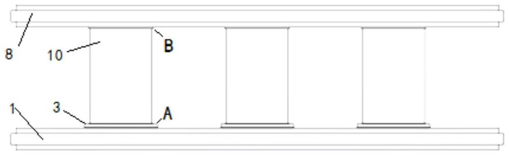
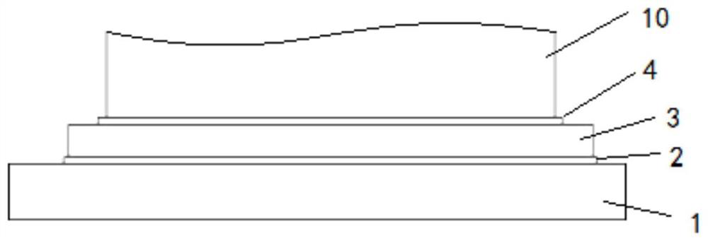
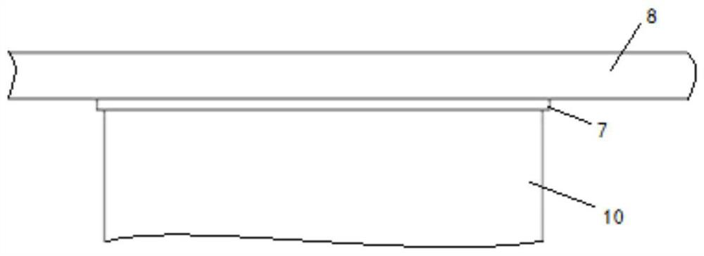
[0040] Such as Figure 4 As shown, the double-sided heat dissipation power module of this embodiment includes a power chip 3, an upper backing board 8, a lower backing board 1 and a spacer assembly 5, and one side of the power chip 3 is connected to the lower backing board 1 through the first connection layer 2. The other side of the power chip 3 is connected to one end of the spacer assembly 5 through the second connection layer 4, and the other end of the spacer assembly 5 is connected to the upper liner 8 through the third connection layer 7; wherein the spacer assembly 5 includes The first spacer 501 and the second spacer 502, one end of the first spacer 501 is connected to the power chip 3 through the second connection layer 4, and the other end of the first spacer 501 is detachably connected to one end of the second spacer 502 , the other end of the second pad 502 is connected to the upper liner 8 through the third connection layer 7 . The double-sided heat dissipation ...

Embodiment 2

[0059] The difference between this embodiment and the first embodiment lies in that the shapes of the bump 601 and the groove 602 are different. Specifically, the bump 601 is convex, and the groove 602 matches the bump 601 to be convex. The specific process is:

[0060] Connect the power chip 3 to the lower substrate 1 through the first connection layer 2, and then connect the first spacer 501 (with bump 601) on the power chip 3 through the second connection layer 4; The second pad 502 (with groove 602) is connected to the upper liner 8; the above three connection processes are reflow soldering or sintering processes, and the thickness of the connecting layer in the above three reflow soldering or sintering processes does not need to be specially increased. Thick; after completing the three-step connection, connect the first spacer 501 and the second spacer 502 of the two parts of the product by sliding, because the protrusions 601 and grooves 602 of each spacer cooperate wit...


PUM


Abstract

The invention discloses a double-sided heat dissipation power module and a packaging method thereof. The module comprises a power chip, an upper lining plate, a lower lining plate and a cushion blockassembly, wherein one side of the power chip is connected with the lower lining plate through a first connecting layer, and the other side of the power chip is connected with one end of the cushion block assembly through a second connecting layer; the other end of the cushion block assembly is connected with the upper lining plate through a third connecting layer, the cushion block assembly comprises a first cushion block and a second cushion block, one end of the first cushion block is connected with a power chip through a second connecting layer, and the other end of the first cushion blockis detachably connected with one end of the second cushion block; and the other end of the second cushion block is connected with the upper lining plate through a third connecting layer. The inventionhas the advantages of reducing the process difficulty, being convenient to connect, ensuring the heat-conducting capability, reducing the cost and the like.

Description

technical field [0001] The invention mainly relates to the technical field of power semiconductor devices, in particular to a double-sided heat dissipation power module and a packaging method thereof. Background technique [0002] The general double-sided heat dissipation power module uses an integrally formed copper block as a pad to complete the heat conduction and conduction functions, such as figure 1 shown. Double-sided heat dissipation power modules generally require three connection processes. The first time is to connect the power chip 3 to the lower substrate 1 through the first connection layer 2; the second time is to connect one end of the spacer 10 through the second connection layer 4 connected to the power chip 3, such as figure 2 Shown; The third time is that the upper liner 8 is connected to the other end of the spacer 10 through the third connecting layer 7, as image 3 shown. In this technological process, there are following problems: [0003] 1. Be...

Claims


Application Information

Patent Timeline
Patent Type & Authority Applications(China)
IPC IPC(8): H01L23/367H01L21/52H01L21/54H01L25/07
CPCH01L23/367H01L21/52H01L21/54H01L25/072H01L2224/33181H01L2224/32225
Inventor 刘亮齐放柯攀戴小平
Owner 湖南国芯半导体科技有限公司
Why Eureka
Try Eureka