A control method and device for a dual active bridge dc-dc converter without DC bias

A DC-DC, no DC bias technology, applied in the direction of output power conversion device, DC power input conversion to DC power output, control/regulation system, etc., can solve the problem of reducing the size of dual active bridge DC-DC converters Problems such as volume, unusability, and complex design can be solved to achieve the effects of speeding up transient response, improving reliability, and enhancing stability

Active Publication Date: 2021-08-24
SOUTHWEST JIAOTONG UNIV
View PDF8 Cites 0 Cited by
  • Summary
  • Abstract
  • Description
  • Claims
  • Application Information

AI Technical Summary

Problems solved by technology

[0004] Aiming at the problem that the dual active bridge DC-DC converter cannot be used when a DC bias current occurs, and the disadvantages of complex design and high cost in the traditional method of suppressing the traditional DC bias current, the present invention proposes a DC-free A control method and device for a biased dual active bridge DC-DC converter, applying discrete phase-shift control to a dual active bridge DC-DC converter, and performing DC bias optimization on it, so that the dual active bridge The DC-DC converter has no DC bias generation when the load and input voltage change suddenly and two discrete control pulse groups switch, and the dynamic response speed is fast; and the control technology proposed by the present invention is simple and easy to implement, and has strong stability and anti-interference ability; The DC blocking capacitor traditionally used to suppress the bias current is removed, and the volume of the dual active bridge DC-DC converter is significantly reduced

Method used


Image

  • A control method and device for a dual active bridge dc-dc converter without DC bias
  • A control method and device for a dual active bridge dc-dc converter without DC bias
  • A control method and device for a dual active bridge dc-dc converter without DC bias

Examples


Embodiment Construction

[0081] The present invention will be described in further detail below with reference to the accompanying drawings and specific embodiments. Specific details in the embodiments described below, such as specific circuit structures in the embodiments, and specific parameters of these circuit elements, are used to provide a better understanding of embodiments of the present invention. Those skilled in the art will appreciate that embodiments of the present invention can also be implemented even in the case where some details, components, components, materials, and the like are lacking.

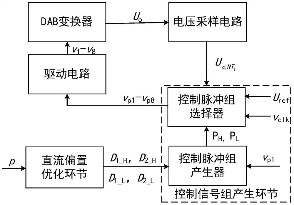
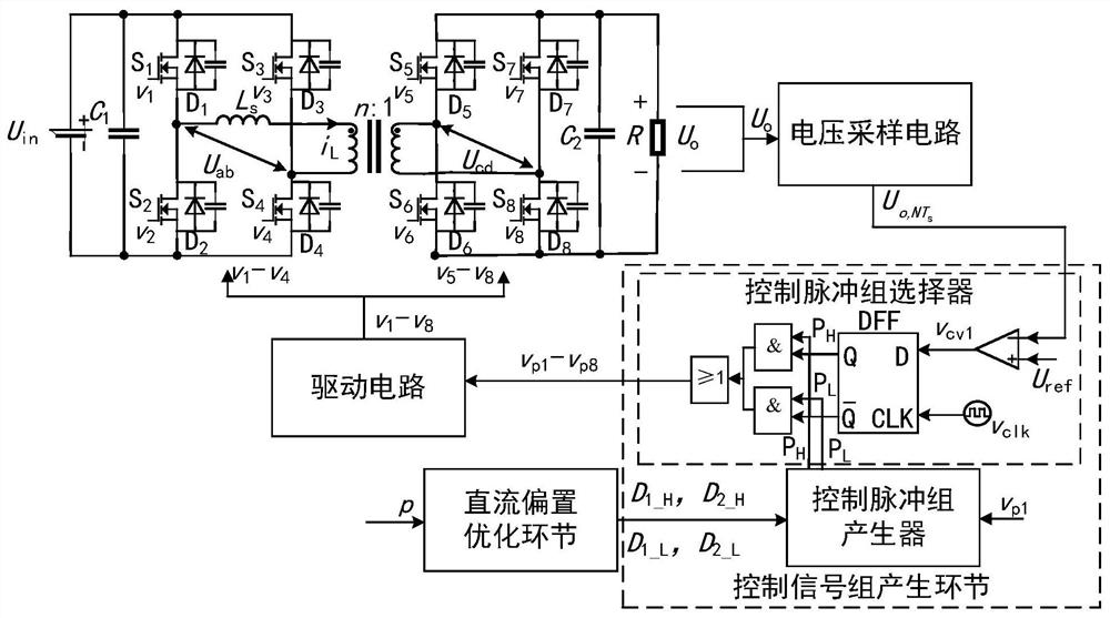
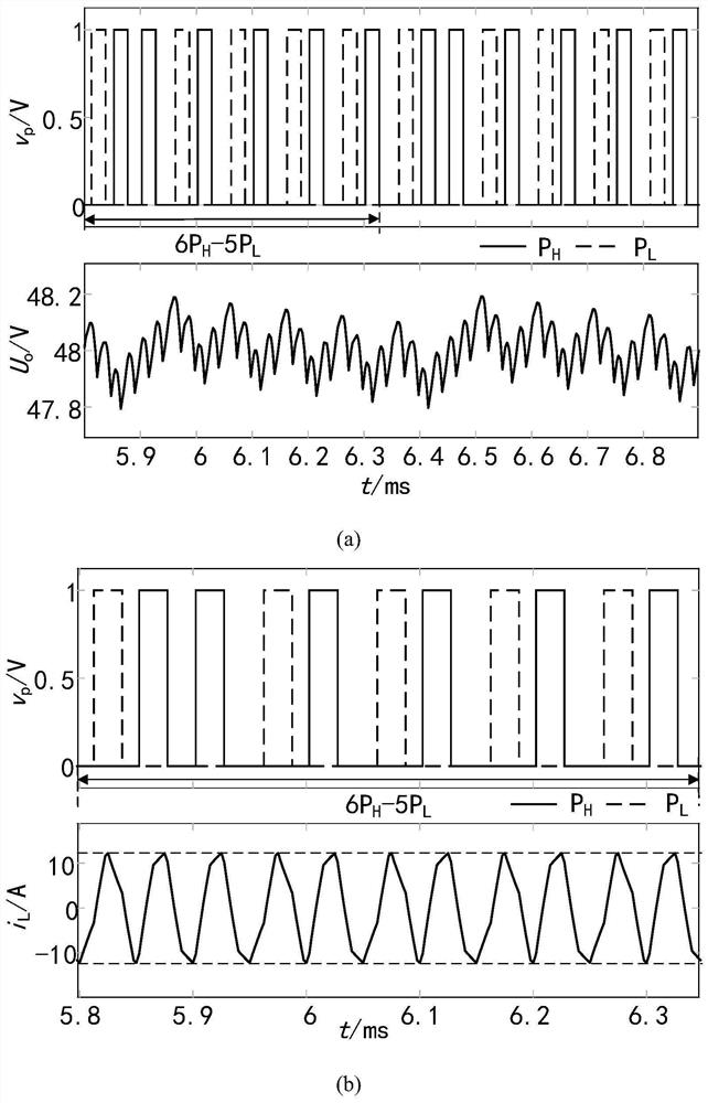
[0082] The present invention proposes discrete phase control to a dual active bridge DC-DC converter for solving its DC bias current problem, wherein the dual active bridge DC-DC converter includes a transformer, and is connected to the transformer The primary side H bridge and sub-edge H bridge, the original h-bridge, the original h-bridge and the secondary H bridge, including two bridge arms, a tot...


PUM


Abstract

A control method and device for a dual active bridge DC-DC converter without DC bias, in which a high-power phase-shift control pulse group P is set according to the condition that the inductor current is equal during half a switching cycle H The primary side of the dual active bridge DC‑DC converter is shifted inwards compared to D 1H Compared with the outward shift between the primary side and the secondary side D 2H , and low-power phase-shift control pulse group P L The primary side of the dual active bridge DC‑DC converter is shifted inwards compared to D 1L Compared with the outward shift between the primary side and the secondary side D 2L , to ensure that no DC bias is generated; then the standard switching tube control signal according to D 1H and D 2H Perform phase shifting to obtain the control signals of the remaining switch tubes to form P H , the standard switching tube control signal according to D 1L and D 2L Perform phase shifting to obtain the control signals of the remaining switch tubes to form P L ; Finally, at the beginning of each sampling period according to U o with the output voltage reference value U ref The comparison results from P H and P L Select the appropriate output for controlling the switching tube of the dual active bridge DC-DC converter, so that U o Fast and stable at U ref , fast dynamic response.

Description

Technical field [0001] The present invention belongs to the field of power electronics, and the control method and apparatus of a dual active bridge DC-DC converter with a non-flow biased. Background technique [0002] In the early 1990s, the DUAL Active Bridge (DAB) DC-DC converter was proposed by Doncker. Because of its high power density, energy bidirection flow, easy to achieve soft switches, high reliability, and wide application in the field of fuel cells, electric vehicles. However, since the switch tube parameters of the DAB converter may cause disturbances in a steady state or change their control variables, they may cause the DC bias current of the transformer, and the excessive DC bias current will cause the switch to be burned. Inductors and transformers can be used to reach magnetic saturation and cannot be used. The traditional method of suppressing DC bias current is series-separated capacitance, which increases the volume and cost of the system. [0003] In applic...

Claims


Application Information

Patent Timeline
Patent Type & Authority Patents(China)
IPC IPC(8): H02M3/335
CPCH02M3/33584H02M1/0054Y02B70/10
Inventor 沙金陈丽蓉周国华
Owner SOUTHWEST JIAOTONG UNIV
Why Eureka
Try Eureka