
Feeding and taking equipment for hardware electroplating

A technology for hardware and equipment, which is applied in the field of material loading and unloading equipment for hardware electroplating, which can solve the problems of messy overall screw angles, damage to the electroplating layer of screws, and reduced internal clamping area, etc.

Inactive Publication Date: 2021-01-26
广州九岳天装饰工程有限公司
View PDF0 Cites 0 Cited by
  • Summary
  • Abstract
  • Description
  • Claims
  • Application Information

AI Technical Summary

Problems solved by technology

[0004] Aiming at the deficiencies in the prior art, the object of the present invention is to provide a loading and unloading device for hardware electroplating, so as to solve the problems caused by the randomness of the screws when the current loading and unloading equipment for hardware electroplating in the prior art picks up hardware screws. Irregular placement, so that the overall angle of the screws is different and relatively messy. When the equipment is picked up, the clamping jaws can only clamp one-to-one screws. If the clamping jaws clamp multiple screws at the same time, it is easy to cause different clamping areas on the front and rear of the screws. , leading to a reduction in the internal clamping area, resulting in different friction forces, resulting in friction and extrusion on the surface between the screw and the clamp arm, resulting in the destruction of the electroplating layer on the surface of the electroplated screw, and resulting in a low pass rate of electroplated screw products. question

Method used


Image

  • Feeding and taking equipment for hardware electroplating
  • Feeding and taking equipment for hardware electroplating
  • Feeding and taking equipment for hardware electroplating

Examples


Embodiment 1

[0026] as attached figure 1 to attach Figure 5 Shown:

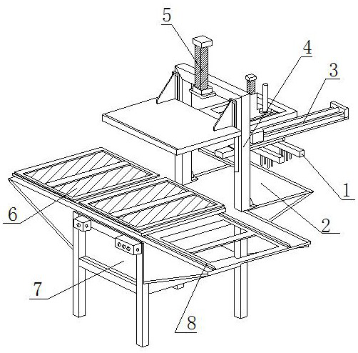
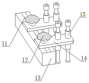
[0027] Its structure includes a suction frame 1, a stage 2, a slideway 3, a gantry frame 4, an air pump 5, a pick-up grid 6, a support seat 7, and a guide rail 8. The surface of the suction frame 1 and the slideway 3 are movable, and the The stage 2 is fixed on the upper surface of the support seat 7, and is embedded and connected with it, the gantry 4 is connected with bolts on both sides of the slideway 3, the air pump 5 is connected with the top of the gantry 4 with bolts, and the object picking grid 6 is fixed The upper end of the support seat 7 is clearance fit, the surface of the support seat 7 is embedded and connected with the guide rail 8, and the guide rail 8 is slidingly matched with the bottom end of the object picking grid 6. The suction frame 1 includes a positioning groove 11, an adjustment bolt 12, a frame Rod 13, fixed plate 14, absorbing roller 15, the inside of the positioning groove 11 is connected ...

Embodiment 2

[0034] as attached Figure 6 to attach Figure 7 Shown:

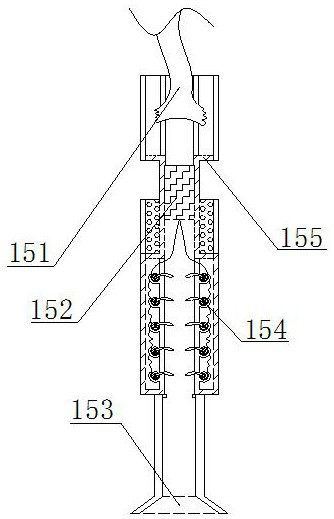
[0035] Wherein, the storage opening 153 includes the inner wall b1 of the roller, the correction ring b2, the positioning rod b3, and the telescopic plate b4, the inner wall of the correction ring b2 is welded to the surface of the telescopic plate b4, and the positioning rod b3 is embedded and connected to the inner wall b1 of the roller , the inner wall b1 of the roller is embedded and connected with the expansion plate b4, and the correction ring b2 is movably matched with the outer wall of the positioning rod b3. Welding connection, wherein the correction ring b2 is conducive to swinging the sucked screw so that the big end is facing upwards, preventing the bottom from entering the interior of the device first.

[0036] Wherein, the correction ring b2 includes a rubber strip b21, a shrapnel b22, a slot b23, and a swing rod b24. The rubber strip b21 is in clearance fit with the top of the swing rod b24, and the sna...


PUM


Abstract

The invention discloses feeding and taking equipment for hardware electroplating. The equipment structurally comprises a suction frame, an objective table, a slide, a portal frame, an air pump, a taking grid, a support seat and a guide rail, wherein the suction frame is movably matched with the surface of the slide; the objective table is fixed on the upper end surface of the support seat and is fixedly embedded with the support seat; the portal frame is in bolted connection with the two sides of the slide through; the air pump is in bolted connection with the top end of the portal frame; thetaking grid is fixed at the upper end of the support seat in a clearance fit mode; the surface of the support seat is fixedly connected to the guide rail in an embedded mode; the guide rail is in sliding fit with the bottom end of the taking grid; the suction frame comprises a positioning groove, an adjusting bolt, a frame rod, a fixing plate and a suction roller; the interior of the positioning groove is in bolted connection with the adjusting bolt; and the positioning groove is connected to the central position of the upper surface of the frame rod in an embedded mode. According to the equipment, machined electroplating screws are effectively sucked and clamped in a one-to-one correspondence mode, and the problem that due to the fact that clamping jaw type screws with multiple jaws are different in contact area, friction force is different, and an electroplated layer which is just electroplated is rubbed to be damaged is solved.

Description

technical field [0001] The invention relates to the field of metal electroplating, in particular to a material loading and unloading device for metal electroplating. Background technique [0002] Electroplating refers to the process of plating a layer of other metals or other alloys on the metal surface by using the principle of electrolysis. The process of using electrolysis to attach a layer of metal film to the surface made of metal or other materials, so as to prevent corrosion and improve the resistance to corrosion. Abrasiveness, etc., after electroplating, it can also increase the aesthetic effect of electroplating equipment; [0003] However, there are the following deficiencies in the prior art: when the current loading and unloading equipment for hardware electroplating is picking up hardware screws, due to the random and irregular placement of the screws, the overall angle of the screws is not uniform and relatively messy, the equipment can only pick up the materi...

Claims


Application Information

Patent Timeline
IPC IPC(8): B65G47/91
CPCB65G47/912B65G47/918
Inventor 胡杰
Owner 广州九岳天装饰工程有限公司
Learn More