Rope brake suitable for pulleys

A technology of brakes and ropes, applied in transportation, packaging, elevators, etc., can solve the problems of partial wear of brake pads, large damage and jumping of rope clamping blocks and traction wire ropes, and achieve the effect of preventing overspeed operation

Active Publication Date: 2021-01-26
淮北智行信息科技有限公司
View PDF10 Cites 1 Cited by
  • Summary
  • Abstract
  • Description
  • Claims
  • Application Information

AI Technical Summary

Problems solved by technology

For traditional elevators, a speed limiter must be used to monitor and control the downward overspeed of the car at any time. However, with the use of elevators, people have found that the danger of the car overspeeding upward and reaching the top does exist. The reason is that the car is empty. Or when the load is extremely small, the weight of the counterweight side is greater than that of the car. Once the brake fails or the shaft, key, pin, etc. Overspeed occurs, so people study a device that acts on the car, counterweight, wire rope system (suspension rope or compensation rope) or traction sheave, so a rope clamp appears to prevent accidental movement of the car. Vicious casualty accidents, improve the safety of elevator use
[0003] Most of the existing wire rope brakes are upward overspeed protectors. The existing problems are, first of all, the existing wire rope brakes are unilaterally operated, and the brake pads will be eccentrically worn, and the number of times the elevator is used is countless. The long-term movement of the steel wire rope will cause serious partial wear of the brake pads, which will easily cause the brake pads to fail during braking, and at the same time reduce the service life of the wire rope clamp. Moreover, the elevator does not only have the situation of overspeeding in the upward direction during operation. In fact, the elevator There is a possibility of two-way overspeed; secondly, the action of the existing rope gripper is completed in an instant, which is very cruel and has a strong impact, especially when the counterweight often jumps very seriously during the action. The wire rope is damaged more, so the life of the rope clamp is generally shorter

Method used


Image

  • Rope brake suitable for pulleys
  • Rope brake suitable for pulleys
  • Rope brake suitable for pulleys

Examples


Embodiment Construction

[0021] The following will clearly and completely describe the technical solutions in the embodiments of the present invention with reference to the accompanying drawings in the embodiments of the present invention. Obviously, the described embodiments are only some, not all, embodiments of the present invention. Based on the embodiments of the present invention, all other embodiments obtained by persons of ordinary skill in the art without making creative efforts belong to the protection scope of the present invention.

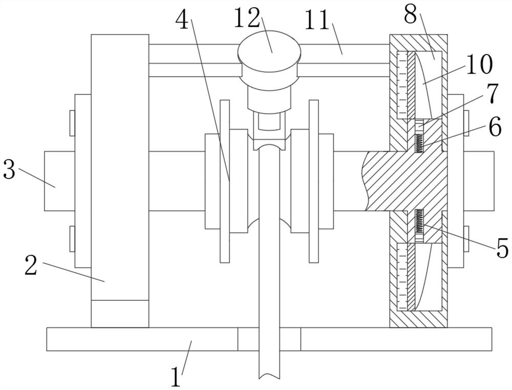
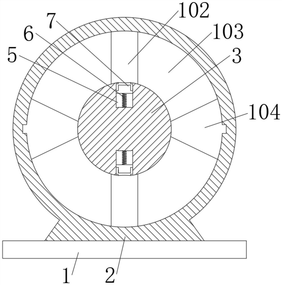
[0022] see Figure 1-7 , a rope brake suitable for pulleys, comprising a base 1, brackets 2 are fixedly connected to both sides of the upper end of the base 1, the middle parts of the two brackets 2 are movably socketed to a rotating shaft 3, and the middle part of the rotating shaft 3 is fixedly connected to a pulley 4, the rotating shaft Both sides of 3 are provided with a group of vertically symmetrical limiting chambers 5, the bottom of the limiting chambe...


PUM


Abstract

The invention relates to the technical field of rope braking equipment, and discloses a rope brake suitable for pulleys. The rope brake suitable for the pulleys comprises a base, wherein supports arefixedly connected to the two sides of the upper end of the base separately; rotating shafts are movably connected to the middle parts of the two supports in a sleeving manner; and the pulleys are fixedly connected to the middle parts of the rotating shafts. Through the cooperation of the pulleys, clamping blocks and a driving ring, when the rotating shafts are driven by the rope to rotate quicklyto generate a large centrifugal force, the clamping blocks can stretch out and press arc-shaped slope surfaces under the rotating action, and the higher the rotating speeds of the rotating shafts are,the higher the moving speed of the rope is, the longer the moving distances of the clamping blocks on the arc-shaped slope surfaces are, and the larger the pressing distance and force of a locking arc plate are; the rope is forced to stop moving and be clamped through the clamping of the clamping blocks on the rotating shafts and the pressure of the locking arc plate, and the arc-shaped slopes are arranged at the two sides of the clamping groove, so that the rope can be clamped no matter whether the rope moves upwards or downwards at an overspeed; and meanwhile, due to the arrangement for thearc-shaped slope surfaces, the rope gripper can be suitable for braking ropes with different thicknesses.

Description

technical field [0001] The invention relates to the technical field of rope braking equipment, in particular to a rope brake suitable for pulleys. Background technique [0002] The rope brake is a rope clamp, which is a braking tool suitable for clamping various ropes such as traditional steel wire ropes and preventing them from running at overspeed. For traditional elevators, a speed limiter must be used to monitor and control the downward overspeed of the car at any time. However, with the use of elevators, people have found that the danger of the car overspeeding upward and reaching the top does exist. The reason is that the car is empty. Or when the load is extremely small, the weight of the counterweight side is greater than that of the car. Once the brake fails or the shaft, key, pin, etc. Overspeed occurs, so people study a device that acts on the car, counterweight, wire rope system (suspension rope or compensation rope) or traction sheave, so a rope clamp appears t...

Claims


Application Information

Patent Timeline
Patent Type & Authority Applications(China)
IPC IPC(8): B66B5/18B66B5/04
CPCB66B5/185B66B5/04
Inventor 渠广波
Owner 淮北智行信息科技有限公司
Why Eureka
Try Eureka