Riding well with high safety
A horse-riding well and safety technology, applied in the field of horse-riding wells, can solve problems that are prone to hypoxia and affect personal safety, and achieve the effect of improving safety, high safety, and increasing oxygen content
- Summary
- Abstract
- Description
- Claims
- Application Information
AI Technical Summary
Problems solved by technology
Method used
Image

Examples
Embodiment Construction
[0020] The technical solutions of the present invention will be further described below in conjunction with the accompanying drawings and through specific implementation methods.
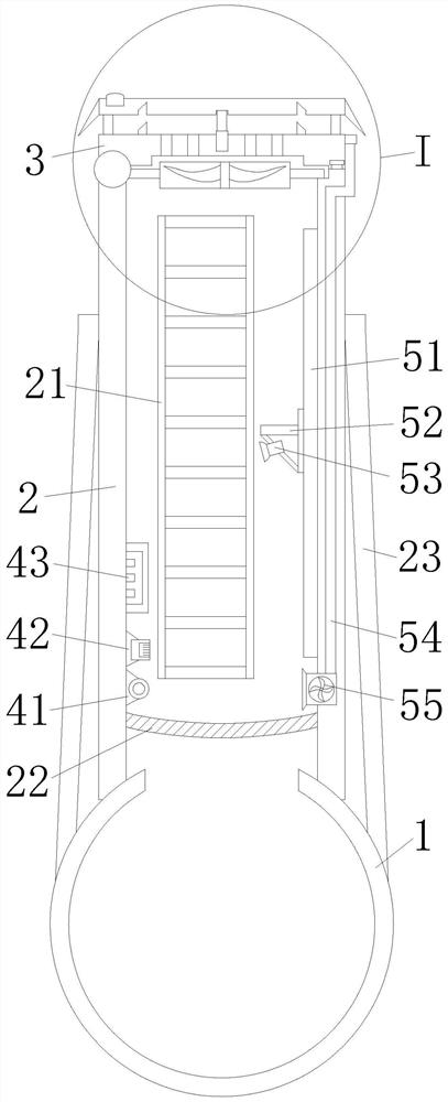
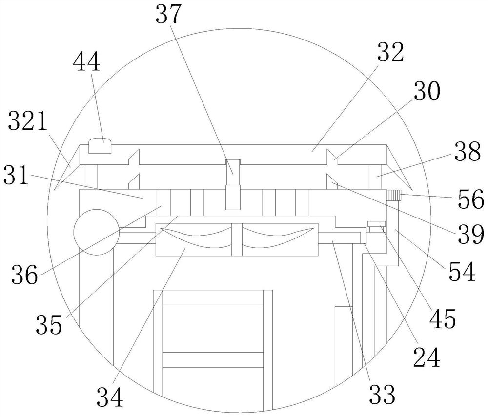
[0021] Such as Figure 1-2 As shown, a high-safety riding well is provided in the embodiment, which includes a riding well 2, a steel casing pipe-jacking pipe section 1, a top cover 3, and ventilation components. Riding well 2 is vertically connected with steel jacket pipe jacking pipe section 1. An opening is provided on the pipe joint 1 of the steel jacket pipe jacking. The opening is arranged in the riding well 2 . The top cover 3 is rotatably connected to the top of the riding well 2 . The ventilation components include an infrared sensor 41 , an oxygen sensor 42 , an air blower, a processor 43 and a hydraulic rod 37 . The top cover 3 includes a cover body 31 , a surface plate 32 and a pole 38 . The bottom of the surface plate 32 is connected to a strut 38 . The lower end of the pole 38 is...
PUM
 Abstract
Description
Claims
Application Information
PatSnap Eureka turns technology decisions into work you can execute. Powered by our Innovation Knowledge Graph, it runs expert workflows across engineering, life sciences, materials and intellectual property. Get your review-ready output in minutes.


