Engine valve production system

A technology for engine valves and production systems, which is applied to closed-circuit television systems, measuring devices, instruments, etc., can solve problems such as inability to adjust assembly line equipment and real-time monitoring of engine valves in product lines, and achieve the effect of preventing overheating and fire.

Inactive Publication Date: 2021-01-26
日照日锻汽门有限公司
View PDF10 Cites 0 Cited by
  • Summary
  • Abstract
  • Description
  • Claims
  • Application Information

AI Technical Summary

Problems solved by technology

[0003] The existing engine valve production cannot monitor the production lin

Method used


Image

  • Engine valve production system
  • Engine valve production system
  • Engine valve production system

Examples


Embodiment Construction

[0023] The following will clearly and completely describe the technical solutions in the embodiments of the present invention with reference to the accompanying drawings in the embodiments of the present invention. Obviously, the described embodiments are only some, not all, embodiments of the present invention.

[0024] Examples of the described embodiments are shown in the drawings, wherein like or similar reference numerals designate like or similar elements or elements having the same or similar functions throughout. The embodiments described below by referring to the figures are exemplary and are intended to explain the present invention and should not be construed as limiting the present invention.

[0025] In describing the present invention, it should be understood that the terms "center", "longitudinal", "transverse", "length", "width", "thickness", "upper", "lower", "front", " Back", "Left", "Right", "Vertical", "Horizontal", "Top", "Bottom", "Inner", "Outer", "Clock...


PUM


Abstract

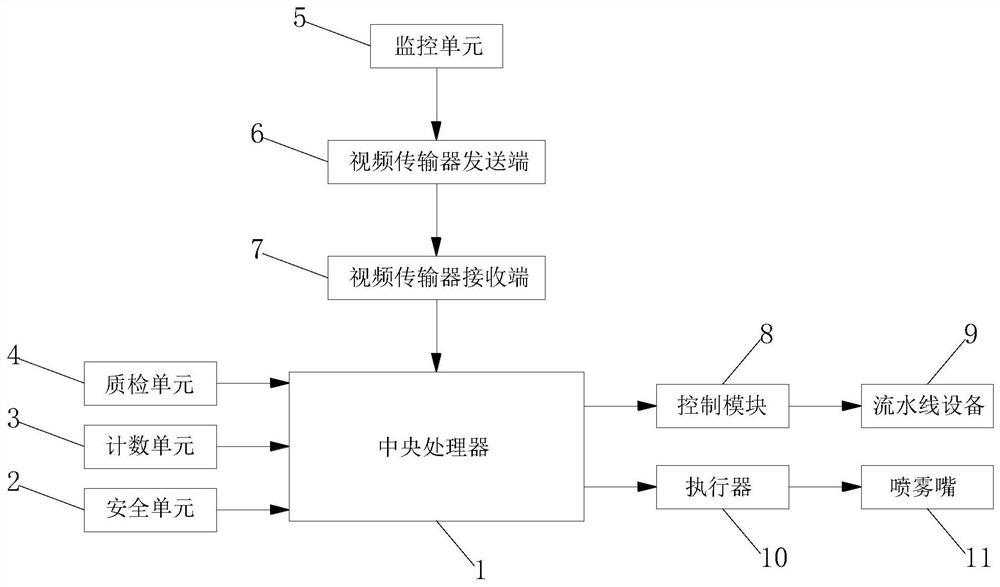
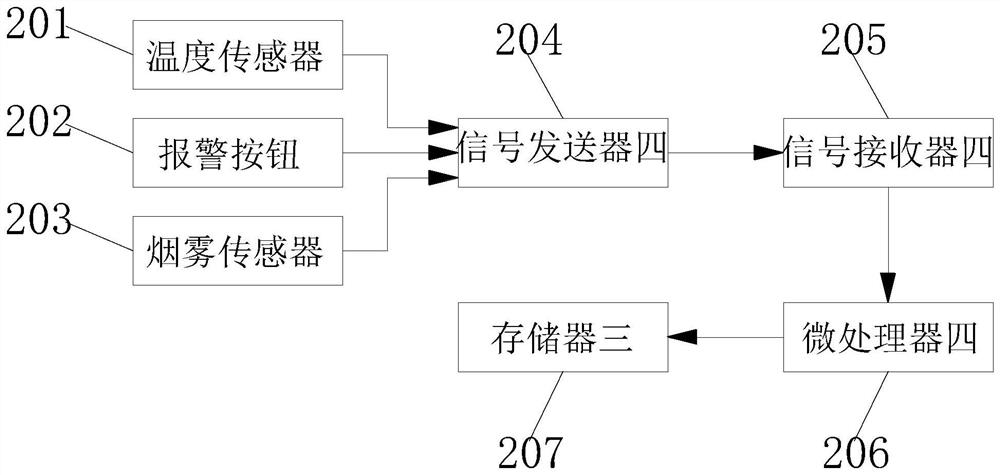
The invention relates to the technical field of engine valve production, and discloses an engine valve production system which comprises a central processing unit, a safety unit, a counting unit, a quality inspection unit and a monitoring unit. The output end of the safety unit is in signal connection with the input end of the central processing unit; the output end of the counting unit is in signal connection with the input end of the central processing unit, the output end of the quality inspection unit is in signal connection with the input end of the central processing unit, the output endof the monitoring unit is in signal connection with the input end of the sending end of the video transmitter, and the output end of the video transmitter transmitting end is in signal connection with the input end of the video transmitter receiving end. Assembly line equipment is monitored through the monitoring unit, then video signals are transmitted to the central processing unit through thevideo transmitter transmitting end and the video transmitter receiving end, and then workers can correspondingly adjust and control the assembly line equipment through the control module.

Description

technical field [0001] The invention relates to the technical field of engine valve production, in particular to an engine valve production system. Background technique [0002] The function of the valve is to be responsible for inputting air into the engine and discharging the exhaust gas after combustion. From the structure of the engine, it is divided into intake valve and exhaust valve. The role of the intake valve is to draw air into the engine and mix it with fuel for combustion; the role of the exhaust valve is to discharge the burned exhaust gas and dissipate heat. [0003] The existing engine valve production cannot monitor the production line in real time, so that the assembly line equipment cannot be adjusted in time. Contents of the invention [0004] (1) Solved technical problems [0005] Aiming at the deficiencies of the prior art, the present invention provides an engine valve production system to solve the problems raised in the background art above. ...

Claims


Application Information

Patent Timeline
IPC IPC(8): G01D21/02A62C31/00A62C37/40H04N7/18
CPCG01D21/02A62C31/005A62C37/40H04N7/18
Inventor 文正镐岡村篤山丰恺
Owner 日照日锻汽门有限公司
Why Eureka
Try Eureka