
System and method for providing and managing electricity

a technology of system and equipment, applied in the direction of instruments, wireless architecture usage, measurement using digital techniques, etc., can solve the problems of reducing efficiency, reducing efficiency, and relying too heavily on individual purchasing decisions and usage tendencies, so as to reduce energy waste, prevent overheating, and reduce energy consumption

Active Publication Date: 2020-01-14
286 TWO LLC
View PDF8 Cites 0 Cited by
  • Summary
  • Abstract
  • Description
  • Claims
  • Application Information

AI Technical Summary

Benefits of technology

[0007]A system in accordance with a preferred embodiment of the invention includes a plurality of units, which communicate with one or more coordinators, which relays data from the units to a server, and relays commands from the server to the units. Alternatively, the coordinators themselves may initiate and send commands to the units. Preferably, the units have safety mechanisms to prevent overheating, fires, etc., by automatically shutting itself, or the device connected to it, off.
[0008]The system preferably also includes energy saving protocols to reduce energy wasted. For example, the system may use light sensors or heat sensors to automatically adjust the light or heat / air conditioning in a specific room or area by adjusting the current being provided to the respective device.

Problems solved by technology

First, this approach relies too heavily on individual purchasing decisions and usage tendencies.
Even when people have the best intentions to conserve energy and purchase energy efficient light bulbs and appliances, lights are often left on after office hours and appliances are persistently plugged in and sit idle between uses.
Second, in many buildings, electricity usage in common areas is a necessity but most often less than optimized.
Third, currently, there is no known way to monitor energy usage both on a macro level, such as a per floor, or a section of a floor or building, and on a micro level, on a per individual outlet basis to identify inefficient points.
Similarly, even when problems are identified, there is no easy way to communicate a patch to resolve the issue or to alter the usage pattern to quickly achieve the desired results.

Method used


Image

  • System and method for providing and managing electricity
  • System and method for providing and managing electricity
  • System and method for providing and managing electricity

Examples


Embodiment Construction

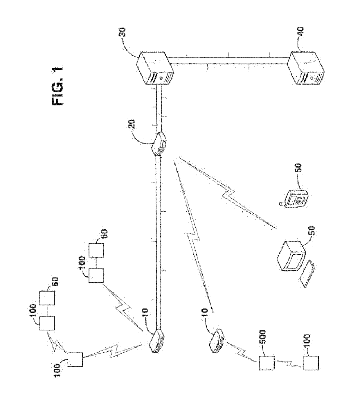
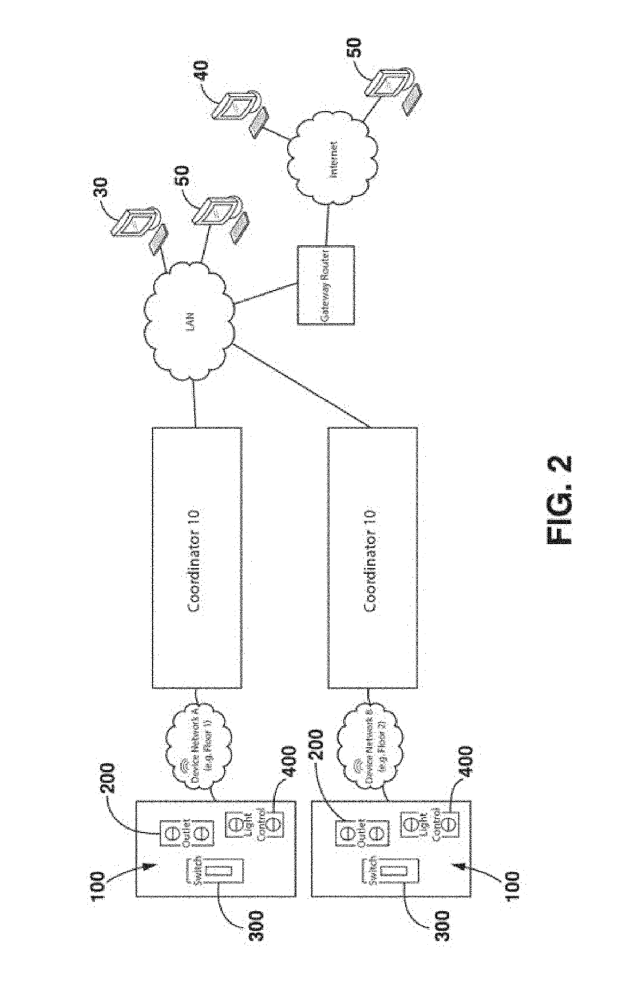
[0068]System Overview. Certain exemplary embodiments of the present invention will now be described with reference to the drawings. Reference is made to FIGS. 1-2, in which a system in accordance with certain embodiments of the invention is shown having a plurality of units 100, a plurality of coordinators 10, a router 20, a local server 30, a remote server 40 and a plurality of communication devices 50.

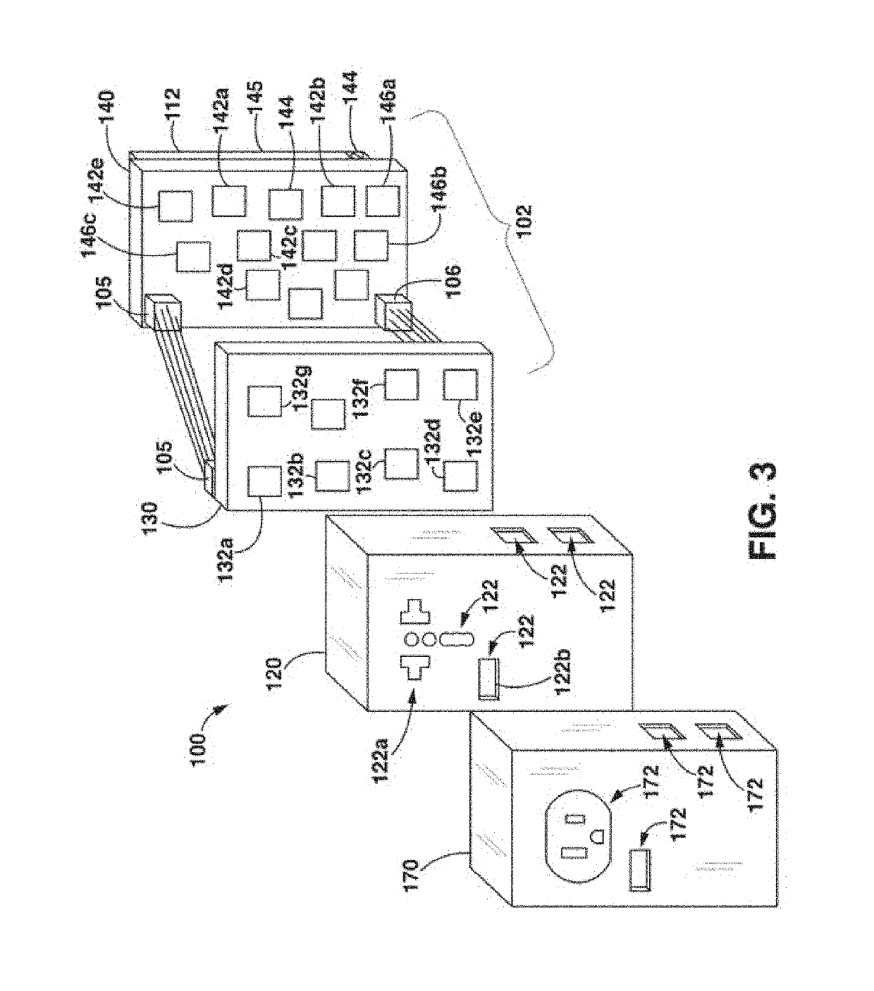
[0069]The units 100 preferably interface with the energy consuming devices 60 in a facility. For example, the units 100 may be connected to lamps, light fixtures, appliances, televisions, fans, or a variety of other electrical units in a room, a house, or a floor of a building, by way of non-liming example. In accordance with an exemplary embodiment, the units 100 can replace existing outlets and switches or be installed in light fixtures or fan controls, preferably designed and constructed to fit into a standard electrical box, thereby facilitating retrofitting of facilities.

[0070]T...


PUM


Abstract

A system and method for providing power to and monitoring the energy usage includes at least one electrical control unit having an unmanned vehicle, at least one electrical control unit, a sensor enabled to monitor a given condition; a power source; a processor configured to be in communication with the at least one sensor and said power source, said processor further configured to manage communications with said management system; an unmanned vehicle releasably coupled to said electrical control unit, said processor being adapted to release said unmanned vehicle to enable the unmanned vehicle to separate from said electrical control unit, wherein said sensor is enabled to monitor at least one of the following: voltage, current, real power, apparent power, reactive power, frequency, total harmonic distortion, arc fault, plug loads, power factor, GFI, AFI, light, temperature, humidity, methane, carbon monoxide, motion, thermal, occupancy, radio frequency, audio, video, infrared, and combinations thereof and wherein said unmanned vehicle can travel to various locations.

Description

CROSS REFERENCE TO RELATED APPLICATION[0001]The application claims the benefit of U.S. Provisional Application No. 61 / 982,752, filed Apr. 22, 2014, entitled, “Miniature Unmanned Aircraft,” which is incorporated by reference herein in its entirety.FIELD OF INVENTION[0002]The present invention is related to a system and apparatus for providing and managing electricity, which system may include as a component, an unmanned aerial vehicle.BACKGROUND OF THE INVENTION[0003]Electricity is an integral part of modern life. Whether in a personal home or a professional office, electricity powers appliances, tools and devices to provide a comfortable and convenient environment for people. However, as human population continues to grow, so has the demand for electricity. Concerned with how such insatiable demand and consumption impact the environment and cause sustainability issues, governments around the world have tried to raise awareness and to promote energy conservation and efficiency.[0004]...

Claims


Application Information

Patent Timeline
Patent Type & Authority Patents(United States)
IPC IPC(8): G05D1/10H04Q9/00G01R15/14B64C27/08B64D47/08B64C39/02G01R22/06G01R19/25
CPCB64D47/08B64C27/08G01R15/142B64C39/024H04Q9/00G05D1/101H04Q2209/40B64C2201/027G01R19/2513B64C2201/06H04Q2209/43G01R22/063B64U50/34B64U10/13
Inventor AMELIO, PAULKATZ, DAVIDAMELIO, ALFONSO
Owner 286 TWO LLC
Learn More