Small mechanical trip type thermal protection piezoresistor

A varistor and thermal protection technology, applied in varistor, overvoltage protection resistors, resistors, etc., can solve the problems of large volume, complex structure, limited application occasions, etc. The effect of fast buckle speed and short air arcing time

Inactive Publication Date: 2019-08-16
陆饶丹
View PDF0 Cites 0 Cited by
  • Summary
  • Abstract
  • Description
  • Claims
  • Application Information

AI Technical Summary

Problems solved by technology

[0011] The purpose of the present invention is to provide a small mechanical trip thermal protection varistor, which aims to solve the technical problems of large volume, complex structure and limited application occasions in the prior art of mechanical trip thermal protection devices

Method used


Image

  • Small mechanical trip type thermal protection piezoresistor
  • Small mechanical trip type thermal protection piezoresistor
  • Small mechanical trip type thermal protection piezoresistor

Examples


Embodiment 1

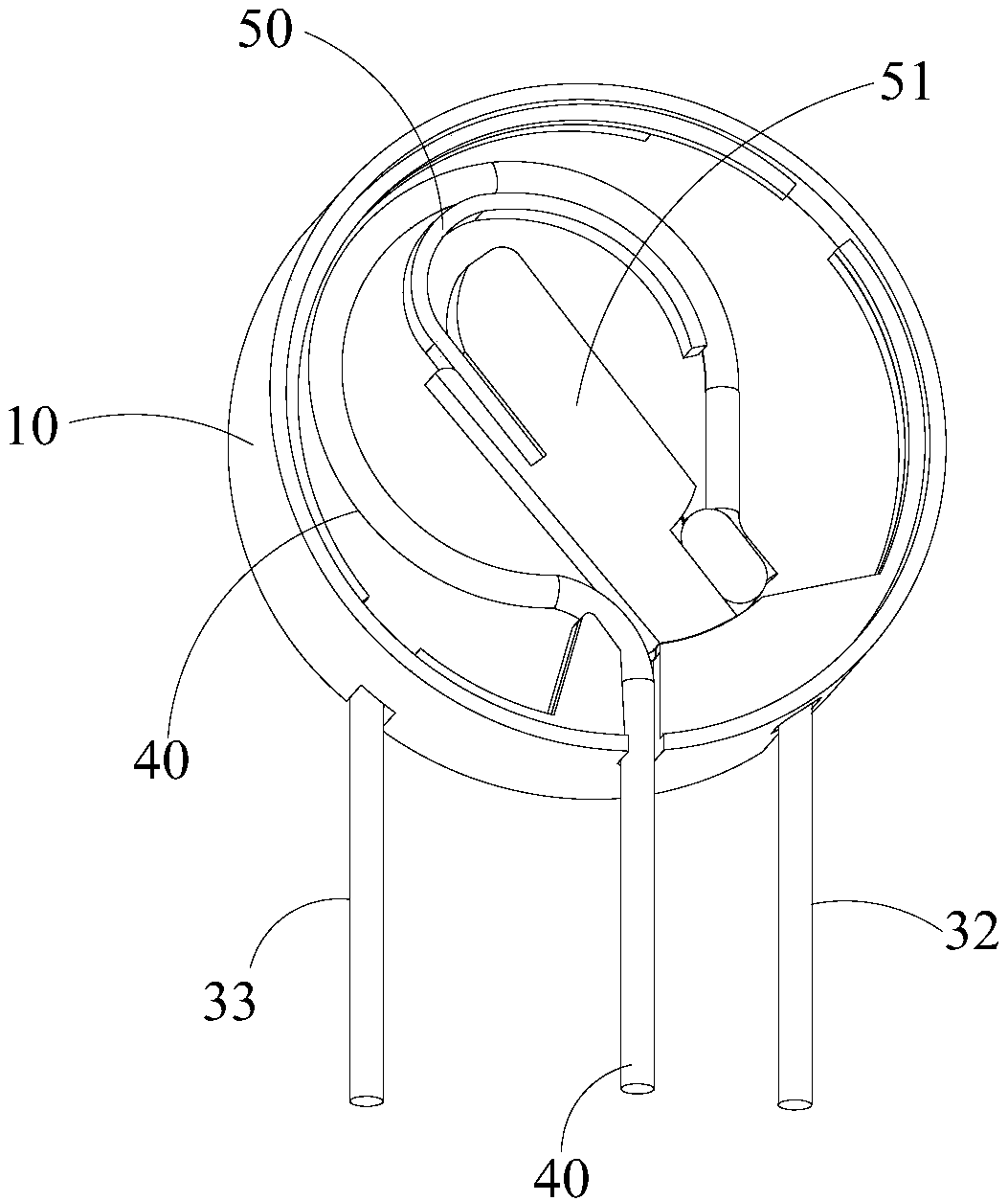
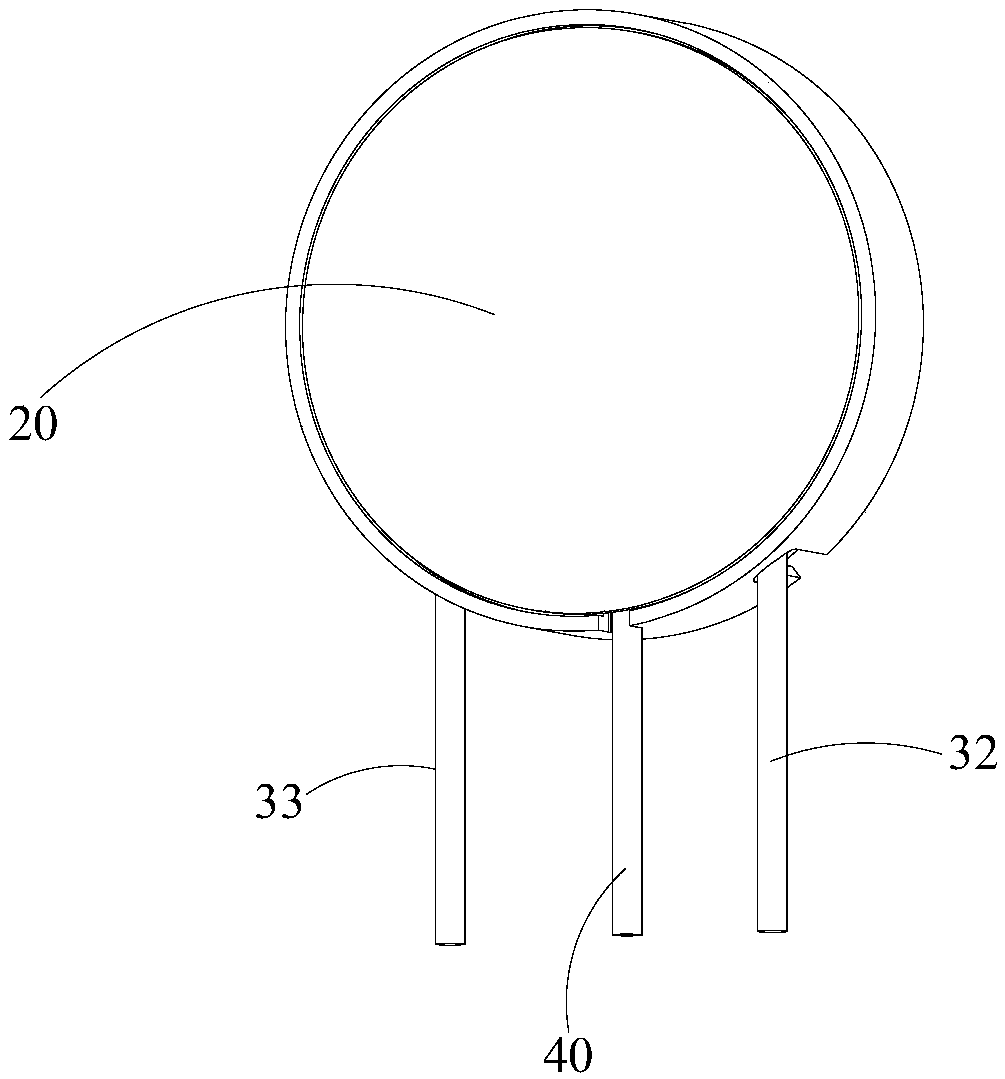
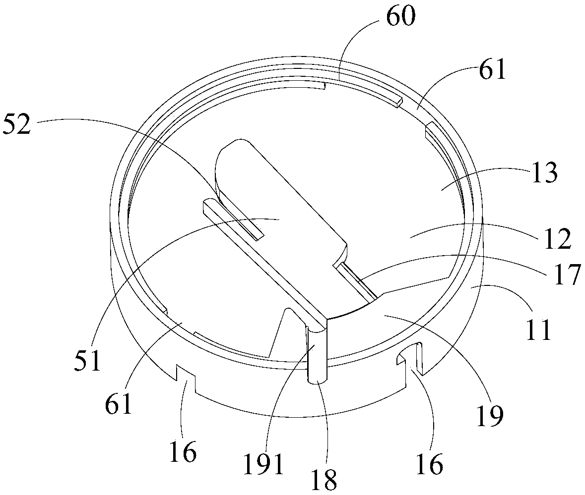
[0043] refer to Figure 1 to Figure 4 , in this embodiment, the base 10 is made of ceramics, which includes a cylindrical shell 11 and a bottom plate 12 placed in the shell 11, the bottom plate 12 divides the shell 11 into a first accommodating cavity 13 on the front side and a back side The second accommodating chamber 14 is provided with a top cover 20 on the upper cover of the first accommodating chamber 13 . The front side and the back side mentioned here refer to the side where the first accommodating cavity 13 of the base 10 is located as the front side, that is, the side where the top cover 20 is installed is the front side, and the opposite side is the back side. The front and back described below are the same as this reference direction and will not be repeated here. Wherein, a movable electrode 40 is disposed in the first accommodation chamber 13 , and a pressure-sensitive valve assembly 30 is disposed in the second accommodation chamber 14 .

[0044] refer to Fi...

Embodiment 2

[0055] refer to Figure 8 The difference between the small mechanical trip thermal protection varistor provided in the second embodiment of the present invention and the first embodiment is that the inner end of the movable electrode 40 is bent in a different shape. Correspondingly, the first receiving chamber 13 The fixed structure is also different. The movable electrode 40 is bent like a torsion spring. Specifically, the inner end of the movable electrode 40 is bent into a ring shape, and then the end extends to the window 17 to be welded and fixed to the exposed part of the first electrode 32 . A circular boss 70 is disposed inside the first receiving chamber 13 , and the ring-shaped bent portion is sheathed on the circular boss 70 . In this way, a double-coil torsion spring with better fatigue resistance is used as the movable electrode 40, which saves the auxiliary detachment shrapnel 60, reduces the number of parts and simplifies the installation process, which is cond...


PUM


Abstract

The invention relates to the technical field of piezoresistors, and provides a small mechanical trip type thermal protection piezoresistor. The piezoresistor comprises a base, a top cover, a pressuresensitive valve plate component and a movable electrode, the front surface of the base is provided with a first holding cavity, the top cover covers the first holding cavity, the back surface of the base is provided with a second holding cavity, the pressure sensitive valve plate component comprises a pressure sensitive valve plate arranged in the second holding cavity and first and second electrodes respectively clamped at the front surface and the back surface of the pressure sensitive valve plate and extended out of the second holding cavity, the first holding cavity is internally providedwith a window configured to allow part of the first electrode to be exposed, the movable electrode is elastic, the inner end of the movable electrode is extended into the first holding cavity, bent, then arranged at the window and welded and fixed with the exposed portion of the first electrode, and the outer end of the movable electrode is extended out of the first holding cavity. The technical problems of the large volume, the complex structure and the limited application occasions of the mechanical trip type thermal protection device in the prior art are solved.

Description

technical field [0001] The invention relates to the technical field of varistors, and in particular provides a small mechanical trip type heat protection varistor. Background technique [0002] As the most commonly used lightning protection component, varistors are widely used in the power ports of various devices to absorb the lightning surge voltage intruded from the power supply cable to the device port and provide lightning protection for the device. Limited by its own heat capacity, the varistor can only absorb transient lightning overvoltage or transient power frequency overvoltage with a certain amount of energy, but cannot withstand long-term continuous overvoltage, otherwise the excessive energy absorbed will cause the varistor to The short-circuit failure of the valve plate due to high temperature will ignite the epoxy resin insulation layer wrapped by its outer layer, resulting in flame or even deflagration. When the varistor is subjected to external over-energy ...

Claims


Application Information

Patent Timeline
Patent Type & Authority Applications(China)
IPC IPC(8): H01C7/12H01C1/022H01C1/144
CPCH01C1/022H01C1/144H01C7/126
Inventor 陆饶丹
Owner 陆饶丹
Why Eureka
Try Eureka