
Sampler capable of automatically adjusting sampling depth

An automatic adjustment and prototyping technology, applied in the direction of sampling devices, etc., can solve the problems of inflexible movement, high labor intensity, inconvenient use, etc., and achieve the effects of increasing overall assembly efficiency, increasing the upper and lower limits of height, and being convenient to use

Pending Publication Date: 2021-01-26
界首市粮食机械有限责任公司
View PDF8 Cites 0 Cited by
  • Summary
  • Abstract
  • Description
  • Claims
  • Application Information

AI Technical Summary

Problems solved by technology

At present, although the existing grain sampling machine that can automatically adjust the depth of sampling can solve the problems of low efficiency, high labor intensity, and unsafety in manual sampling of raw grains, the fixed automatic adjustment sampling machine designed by using the working principle of the tower crane The deep grain sampling machine is inconvenient to use, and the position cannot be moved flexibly

Method used


Image

  • Sampler capable of automatically adjusting sampling depth
  • Sampler capable of automatically adjusting sampling depth
  • Sampler capable of automatically adjusting sampling depth

Examples


Embodiment 1

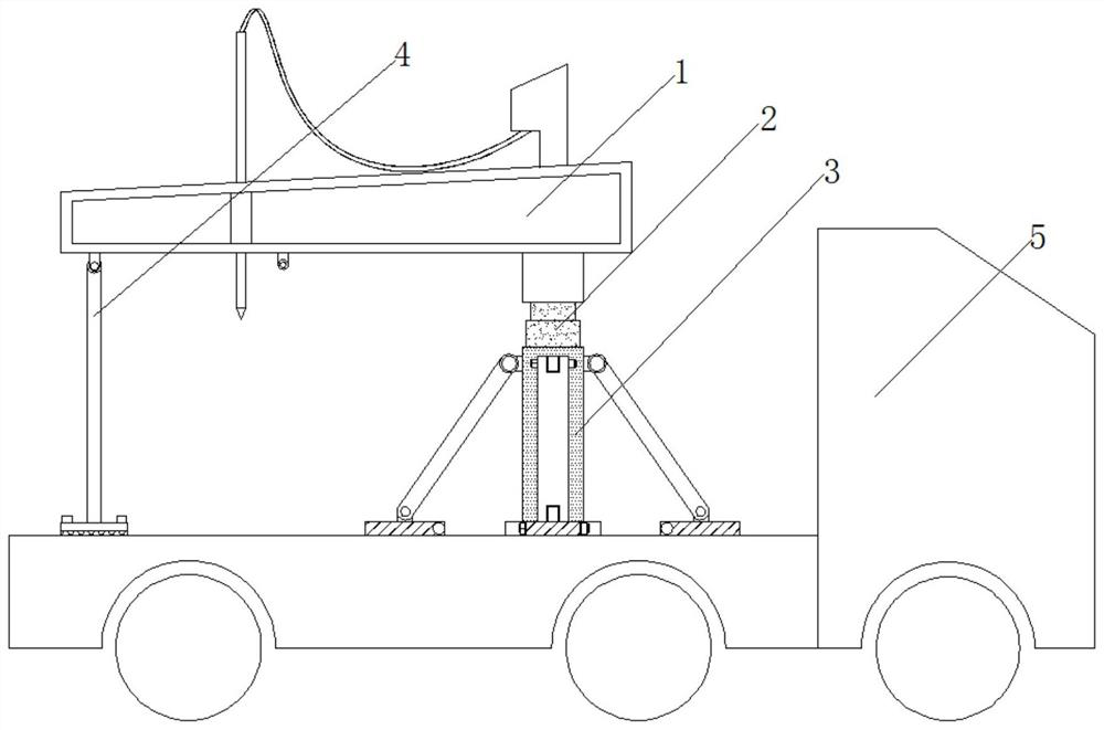
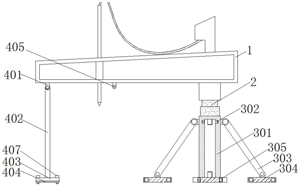
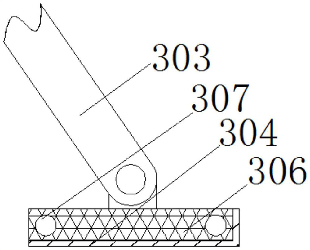
[0025] see Figure 1-4 , a cutting machine with automatic adjustment of cutting depth, comprising a cutting machine 1 and a flat motor vehicle 5, a first telescopic rod 2 is fixedly installed at the bottom of the right end of the cutting machine 1, and a support is arranged below the first telescopic rod 2 Mechanism 3, the support mechanism 3 includes a support column 301, a first bolt 302, a connecting rod 303, a sliding sleeve 304, a second bolt 305, a slider 306, a limit hole 307 and an adjustment hole 308; the bottom of the first telescopic rod 2 is fixed A support column 301 is installed, and the top of the support column 301 is provided with a connecting rod 303. The connecting rod 303 has four groups and is evenly distributed on the top of the support column 301. The top of the connecting rod 303 rotates with the top of the support column 301 through the first bolt 302. Connection, the bottom end of the connecting rod 303 is connected with the slider 306 through the rot...

Embodiment 2

[0028] see figure 1 , 2 , 5 and Image 6 , the cutting machine with automatic adjustment of the cutting depth, the left side of the cutting machine 1 is provided with an auxiliary balance mechanism 4, the auxiliary balance mechanism 4 includes a connecting piece 401, a bracket 402, a fixed plate 403, an anti-skid rubber pad 404, a second telescopic Rod 405, slot 406 and pin 407; the bottom of the left end of the cutting machine 1 is fixedly connected with a connecting piece 401, the bottom of the connecting piece 401 is rotatably connected with a bracket 402, the bottom of the bracket 402 is fixedly connected with a fixed plate 403, and the fixed plate 403 The bottom of the bottom is fixedly connected with a non-slip rubber pad 404; the lower left side of the cutting machine 1 is fixedly equipped with a second telescopic rod 405, and the front end of the second telescopic rod 405 is provided with a card slot 406. The interior of the left and right ends of the fixed plate 403...


PUM


Abstract

The invention discloses a sampler capable of automatically adjusting the sampling depth, and relates to the field of grain samplers. The sampler comprises a sampler body and a flat motor vehicle, a first telescopic rod is fixedly mounted at the bottom of the tail end of the right side of the sampler body, and a supporting mechanism is arranged below the first telescopic rod; and the supporting mechanism comprises a supporting column, a first bolt, a connecting rod, a sliding sleeve, a second bolt, a sliding block, a limiting hole and an adjusting hole. According to the sampler capable of automatically adjusting the sampling depth, through cooperation of the sampling machine and the flat motor vehicle, the sampling machine is effectively changed into a movable sampling machine, so that thesampling machine can move in multiple directions and is convenient to use, the application range of the sampling machine capable of automatically adjusting the sampling depth is widened, and the problem that when an existing tower crane working principle is adopted, the designed fixed grain sampler capable of automatically adjusting the sampling depth is inconvenient to use and cannot be flexiblymoved is solved.

Description

Technical field: [0001] The invention relates to the field of grain cutting machine, in particular to a cutting machine capable of automatically adjusting the cutting depth. Background technique: [0002] With the rapid development of the market economy, more and more grains have been transported in bulk in recent years. At present, there are many problems in grain sampling, such as heavy work, frequent repetitive work, excessive manpower, limited sampling objects, etc. Sampling is an important process to ensure the fair trade of grain and control the production of storage and processing, and it is of great significance to ensure its quality. In recent years, with the large-scale development of grain production, the quality inspection of grain has been paid more and more attention. With the increasingly fierce competition among enterprises, reducing costs and improving work efficiency are important means to enhance competitiveness. At present, although the existing grain c...

Claims


Application Information

Patent Timeline
IPC IPC(8): G01N1/10
CPCG01N1/10
Inventor 王华勤汪福友余强李洋洋杨宝同马文涛程伟
Owner 界首市粮食机械有限责任公司
Learn More