
Artificial vision landmark and coding method thereof

A technology of artificial vision and coding method, which is applied in the field of artificial visual landmarks and their coding, can solve the problems that artificial visual landmarks cannot meet the goals of precise positioning and calibration, and achieve the effects of improving the scope of application, increasing usability, and high precision

Pending Publication Date: 2021-01-26
ZHEJIANG SCI-TECH UNIV
View PDF0 Cites 0 Cited by
  • Summary
  • Abstract
  • Description
  • Claims
  • Application Information

AI Technical Summary

Problems solved by technology

[0003] At present, due to the limitation of the use scene, the existing types of artificial visual landmarks cannot meet the goal of precise positioning and calibration in subsequent image recognition, so designing an artificial visual landmark can better achieve precise positioning and calibration

Method used


Image

  • Artificial vision landmark and coding method thereof
  • Artificial vision landmark and coding method thereof
  • Artificial vision landmark and coding method thereof

Examples


Embodiment Construction

[0027] Below in conjunction with the embodiment described in accompanying drawing, further introduce the present invention,

[0028] First define a few concepts:

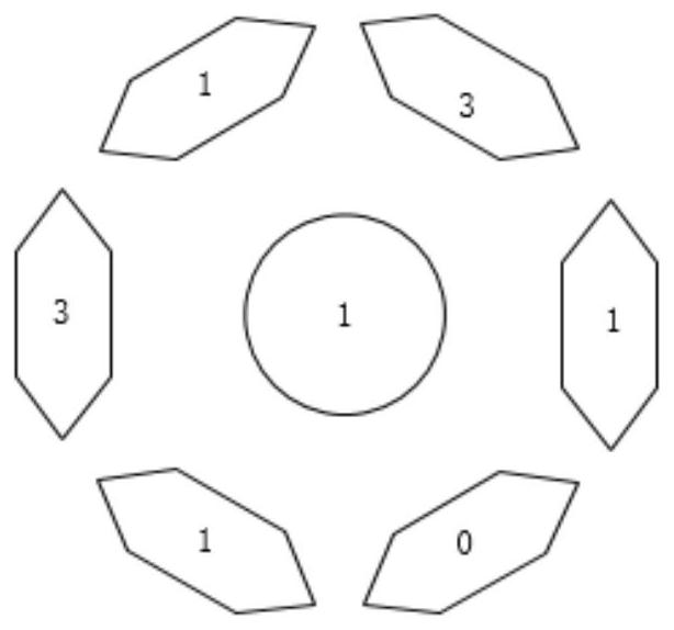
[0029] 1. Center calibration ring: a circular pattern, using one of the four colors of red, green, blue and black.

[0030] 2. Coding block: six hexagonal patterns surrounding the central calibration ring, using one of the four colors of red, green, blue and black.

[0031] 3. Coding sheet: a pattern consisting of a central calibration ring and six coding blocks surrounding the central calibration ring.

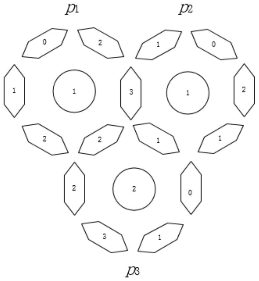
[0032] 4. Artificial visual landmarks: spliced ​​by coded pieces, it is a pattern on the ground that has certain characteristics and can be recognized from the air.

[0033] 5. Repetition: specifically refers to the repetition of the color of the coding chip, that is, the repetition of the code word.

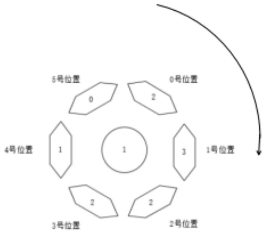
[0034] 6. Coding form: refers to the way of encoding, with a total of eight digits, expressed as numbers + "-" ...


PUM


Abstract

The invention relates to the technical field of camera calibration. The invention aims to provide an artificial vision landmark and a coding method thereof so as to improve the application range of the artificial vision landmark and realize accurate positioning. According to the technical scheme, the artificial vision landmark comprises 1) four or more coding sheets; 2) every two rows and every two columns of all the coding sheets are arranged in a crossed manner, and the coding sheets in each row are linearly arranged in the horizontal direction; 3) any coding sheet comprises a central calibration ring and six coding blocks arranged around the central calibration ring; 4) the central calibration ring is a circular pattern and adopts one color of red, green, blue and black; and 5) the sixcoding blocks are six hexagonal patterns surrounding the central calibration ring, and each coding block adopts one color of red, green, blue and black.

Description

technical field [0001] The invention relates to the technical field of camera calibration, in particular to an artificial visual landmark and a coding method thereof. Background technique [0002] In the image measurement process and machine vision applications, in order to determine the relationship between the three-dimensional geometric position of a point on the surface of a space object and its corresponding point in the image, it is necessary to establish a geometric model of camera imaging, and these geometric model parameters are camera parameters. Under most conditions, these parameters must be obtained through experiments and calculations. This process of solving parameters is called camera calibration (or camera calibration). The artificial visual landmarks used in camera calibration data acquisition include two types of equidistant solid circle array pattern and chessboard pattern, which can realize accurate positioning, recognition and analysis of target images....

Claims


Application Information

Patent Timeline
IPC IPC(8): G06T7/80G06T7/90H04N19/174H04N19/176H04N19/186
CPCG06T7/80H04N19/176H04N19/174H04N19/186G06T7/90
Inventor 喻擎苍龚征绛费焕强陈武查杨
Owner ZHEJIANG SCI-TECH UNIV
Learn More