Power distribution box for electrical engineering

A technology of electrical engineering and distribution box, applied in substation/distribution device casing, electrical components, substation/switch layout details, etc. Improved safety and ease of use

Inactive Publication Date: 2021-01-26
李波
View PDF14 Cites 0 Cited by
  • Summary
  • Abstract
  • Description
  • Claims
  • Application Information

AI Technical Summary

Problems solved by technology

[0003] At present, there are many kinds of distribution boxes for electrical engineering on the market, but these generally have low heat dissipation efficiency and cannot evenly dissipate heat for the electrical components in the distribution box

Method used


Image

  • Power distribution box for electrical engineering
  • Power distribution box for electrical engineering
  • Power distribution box for electrical engineering

Examples


Embodiment 1

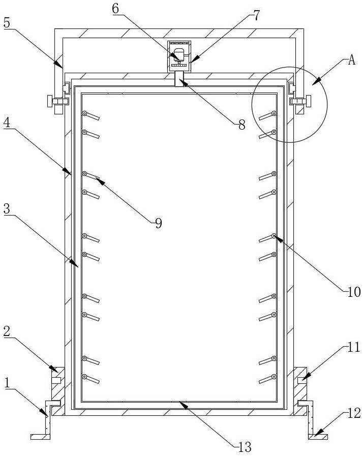
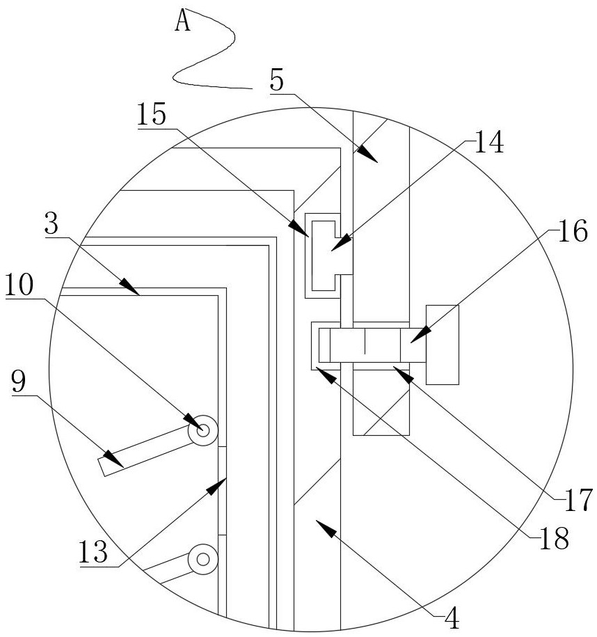
[0024] see Figure 1~3 , in an embodiment of the present invention, a distribution box for electrical engineering includes a distribution box main body 4, a fan casing 7 is connected to the top of the distribution box main body 4, and the top of the distribution box main body 4 is close to the fan casing 7 The position is connected with a connecting pipe 8, the inner side of the distribution box main body 4 is provided with an annular ventilation pipe 3, and the outer side of the annular ventilation pipe 3 is equidistantly provided with several air outlet holes 13, and the outer side of the annular ventilation pipe 3 is equidistantly provided with several pairs of The wind deflector 9 has a damping rotating shaft 10 installed on one side of the wind deflector 9 , and the fan 6 is installed on the inside of the fan casing 7 .

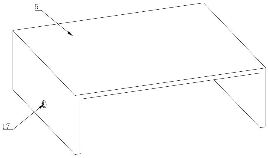
[0025] Wherein, the top of the distribution box main body 4 is provided with a rain shield 5, the tops of both sides of the distribution box main body 4...

Embodiment 2

[0032] refer to figure 1 , a distribution box for electrical engineering. Compared with Embodiment 1, this embodiment also includes two connection plates 2 connected to both sides of the main body 4 of the distribution box, and two connection plates 2 are provided on one side of the connection plate 2. slot 11, one side of the connecting plate 2 is connected with an adjustable support rod 1, and the bottom end of the adjustable support rod 1 is provided with a support seat 12.

[0033] Wherein, one end of the adjustable support rod 1 is arranged inside the limit slot 11 , and the bottom end of the support base 12 is provided with an anti-slip gasket.

[0034] Working principle: When there is water accumulated on the ground where the main body 4 of the distribution box is placed, in order to prevent water from seeping into the main body 4 of the distribution box, the main body 4 of the distribution box can be lifted first, and then the adjustable support rod 1 can be inserted i...


PUM


Abstract

The invention discloses a power distribution box for electrical engineering. The power distribution box comprises a power distribution box main body, wherein the top end of the power distribution boxmain body is connected with a fan shell, the top end of the power distribution box main body is connected with a connecting pipe at a position close to the fan shell, the inner side of the power distribution box main body is provided with an annular ventilation pipe, a plurality of air outlet holes are formed in the outer side of the annular ventilation pipe at equal intervals, a plurality of pairs of air guide plates are arranged on the outer side of the annular ventilation pipe at equal intervals, damping rotating shafts are installed on one sides of the air guide plates, a fan is installedon the inner side of the fan shell, a rain shielding plate is arranged on the top of the power distribution box main body, and sliding grooves are formed in the tops of the two sides of the power distribution box main body. According to the invention, through the annular ventilation pipe, the connecting pipe, the damping rotating shaft, the air guide plates and the air outlet holes, the fan can conveniently and uniformly blow air to electrical elements in the power distribution box, so that the electrical elements in the electrical box can be uniformly cooled, and the cooling efficiency of theelectrical box is improved.

Description

technical field [0001] The invention relates to the technical field of distribution boxes, in particular to a distribution box for electrical engineering. Background technique [0002] Distribution box is assembled in closed or semiclosed metal safe by electrical wiring requirement by switchgear, measuring instrument, protective circuit and auxiliary equipment or in screen width, forms low-voltage distribution equipment. Outdoor distribution box is relatively important in people's life. It is common and is also one of the commonly used distribution boxes when installing lines in distribution stations. Its main function is to place various electrical equipment outdoors to prevent these electrical equipment from being damaged by the harsh natural environment. , The role of distribution boxes in daily life is becoming more and more important. [0003] At present, there are many kinds of distribution boxes for electrical engineering on the market, but these generally have low h...

Claims


Application Information

Patent Timeline
Patent Type & Authority Applications(China)
IPC IPC(8): H02B1/46H02B1/56H02B1/28
CPCH02B1/46H02B1/565H02B1/28
Inventor 李波刘慧
Owner 李波
Why Eureka
Try Eureka