Power line machining device and method

A technology of processing device and processing method, which is applied in the direction of cable installation device, cable installation, electrical components, etc., can solve the problems of slow power cord cutting speed, difficult power cord cutting error, and accurate control, so as to avoid manual cutting , easy to control, and improve the effect of cutting speed

Inactive Publication Date: 2021-01-29
ZHENJIANG CITY HUACHENG ELECTRONICS EQUIP
View PDF0 Cites 0 Cited by
  • Summary
  • Abstract
  • Description
  • Claims
  • Application Information

AI Technical Summary

Problems solved by technology

[0002] As we all know, a power cord processing device and processing method are auxiliary devices for cutting power cords, which are widely used in the field of wire rod processing equipment; due to the different lengths of power cords required by different production environments, solid During the processing of power cords, different lengths need to be cut according to the actual production requirements. Generally, the cutting is done after manual measurement, which leads to a slow cutting rate of power cords. At the same time, the measurement error of each employee is different, resulting in difficult power cord cutting errors. To achieve more accurate control, there is an urgent need for a power cord cutting device to solve the above problems

Method used


Image

  • Power line machining device and method
  • Power line machining device and method
  • Power line machining device and method

Examples


Embodiment Construction

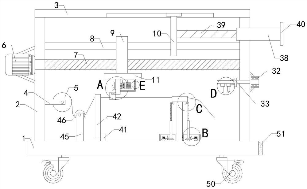
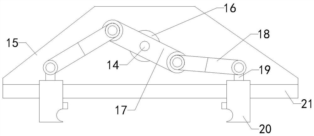
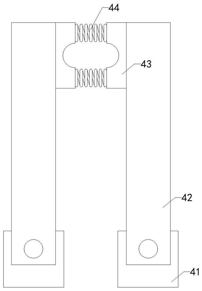
[0022] The specific implementation manners of the present invention will be further described in detail below in conjunction with the accompanying drawings and embodiments. The following examples are used to illustrate the present invention, but are not intended to limit the scope of the present invention.

[0023] Such as Figure 1 to Figure 8As shown, a power cord processing device and processing method of the present invention includes a base 1, two sets of support plates 2, an upper top plate 3, two sets of first fixing blocks 4, a wire pulley 5, a first motor 6, and a screw shaft 7. Slide bar 8, slider 9, T-shaped limit slider 10, adjustment device, installation block 11, protective box 12, second motor 13, reducer 14, second fixed block 15, rotating block 16, two groups The first pendulum block 17, two sets of second pendulum blocks 18, two sets of first shrink rods 19, two sets of first clamping blocks 20, slide rails 21, two sets of motor bases 22, two sets of third m...


PUM


Abstract

The invention relates to the technical field of wire machining equipment, in particular to a power line machining device and method, which can continuously cut a power line with a certain length, avoid manual cutting, facilitate control of cutting errors, improve the cutting speed and save time and labor. The device comprises a base, two groups of supporting plates, an upper top plate, two groupsof first fixing blocks, a wire wheel, a first motor, a lead screw shaft, a sliding rod, a sliding block, a T-shaped limiting sliding block, an adjusting device, a mounting block, a protection box, a second motor, a speed reducer, a second fixing block, a rotating block, two groups of first swing blocks, two groups of second swing blocks, two groups of first contraction rods, two groups of first clamping blocks, a sliding rail, two groups of motor bases, two groups of third motors, two groups of driving helical gears, two groups of driven helical gears, two groups of first screw tubes, two groups of first screw rods, two groups of connecting blocks, two groups of third fixing blocks, a cutting platform, a second contraction rod, a first electric push rod, a fourth fixing block, a fixing plate, two groups of second electric push rods, a cutter and a pressing block.

Description

technical field [0001] The invention relates to the technical field of wire rod processing equipment, in particular to a power cord processing device and a processing method. Background technique [0002] As we all know, a power cord processing device and processing method are auxiliary devices for cutting power cords, which are widely used in the field of wire rod processing equipment; due to the different lengths of power cords required by different production environments, solid During the processing of power cords, different lengths need to be cut according to the actual production requirements. Generally, the cutting is done after manual measurement, which leads to a slow cutting rate of power cords. At the same time, the measurement error of each employee is different, resulting in difficult power cord cutting errors. To achieve more accurate control, there is an urgent need for a power cord cutting device to solve the above problems. Contents of the invention [00...

Claims


Application Information

Patent Timeline
Patent Type & Authority Applications(China)
IPC IPC(8): B21F11/00B21F23/00H02G1/00
CPCB21F11/00B21F23/00H02G1/005
Inventor 孟明华
Owner ZHENJIANG CITY HUACHENG ELECTRONICS EQUIP
Why Eureka
Try Eureka