Field vehicle escape auxiliary equipment
A technology for auxiliary equipment and vehicles, applied in vehicle cleaning equipment, vehicle maintenance, vehicle parts, etc., can solve problems such as four-wheel slipping, four-wheel drive system failure, etc., and achieve the effect of increasing the contact area
- Summary
- Abstract
- Description
- Claims
- Application Information
AI Technical Summary
Problems solved by technology
Method used
Image

Examples
Embodiment Construction
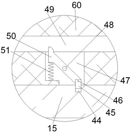
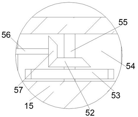
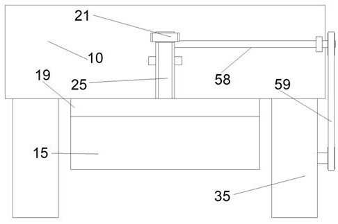
[0016] Combine below Figure 1-4 The present invention is described in detail, wherein, for the convenience of description, the orientations mentioned below are defined as follows: figure 1 The up, down, left, right, front and back directions of the projection relationship itself are the same.
[0017] A kind of off-the-road vehicle escape auxiliary device described in conjunction with accompanying drawings 1-4, comprises a vehicle body 10 and a housing 15 arranged on the lower side of the vehicle body 10, tires 35 are installed at the lower end of the vehicle body 10, and the housing 15 An airbag cavity 37 is provided, and an auxiliary airbag 14 is fixedly installed in the airbag cavity 37. An air pump 40 is fixedly installed in the housing 15. After the air pump 40 is started, it can inflate the auxiliary airbag 14 to make the auxiliary airbag The air bag 14 expands, and the housing 15 is provided with a traction cavity 18, and the traction slide rail 13 is fixedly fixed up...
PUM
 Abstract
Description
Claims
Application Information
PatSnap Eureka turns technology decisions into work you can execute. Powered by our Innovation Knowledge Graph, it runs expert workflows across engineering, life sciences, materials and intellectual property. Get your review-ready output in minutes.


