A roof and air duct integrated module structure for subway vehicles

An integrated module, in-vehicle technology, used in railway roofs, railway vehicle heating/cooling, railway car body components, etc., can solve problems such as the inability of sealing to meet the requirements, the difficulty of further reducing the weight of the interior roof and air ducts, and the lack of assembly accuracy. , to achieve the effect of realizing lightweight design, solving insufficient fresh air volume, and improving assembly efficiency

Active Publication Date: 2022-07-26
CRRC CHANGCHUN RAILWAY VEHICLES CO LTD
View PDF0 Cites 0 Cited by
  • Summary
  • Abstract
  • Description
  • Claims
  • Application Information

AI Technical Summary

Problems solved by technology

[0002] At present, the interior roof and air duct structure of existing subway vehicles are split structures. Since the split structure needs to consider the structural strength of each component separately, it is difficult to further reduce the weight of the interior roof and air duct, which cannot meet the lightweight interior of subway vehicles. design requirements
In addition, there is still a problem of insufficient assembly precision in the roof and air duct structure of the existing subway vehicles. Due to structural constraints, it is difficult to ensure the theoretical gap between the roof and the air duct, which in turn causes a gap between the air supply port of the air duct and the air inlet of the ventilation grille. The sealing cannot meet the requirements, which eventually leads to the problem of insufficient fresh air in the passenger room
[0003] At the same time, the existing subway vehicles need to install two installation processes of air duct and interior roof during the assembly stage
First install the air duct and then install the interior roof plate, and each process requires a separate positioning adjustment, which has problems such as cumbersome installation process, long assembly cycle, and high production cost.

Method used


Image

  • A roof and air duct integrated module structure for subway vehicles
  • A roof and air duct integrated module structure for subway vehicles
  • A roof and air duct integrated module structure for subway vehicles

Examples


Embodiment Construction

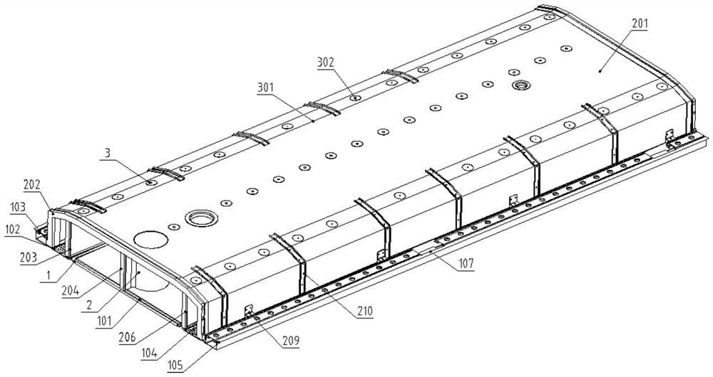
[0027] refer to figure 1 , the specific embodiment of the present invention is an integrated module structure of an interior roof and an air duct of a subway vehicle, including an interior roof structure 1, an air duct structure 2, and a thermal insulation layer 3. The upper side of the interior roof structure 1 and the air duct structure 2. The lower side is bonded and connected by angle iron bolts, and the thermal insulation layer 3 is fixed on the upper surface of the air duct structure 2 by bonding.

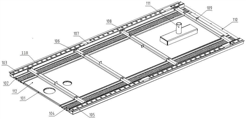
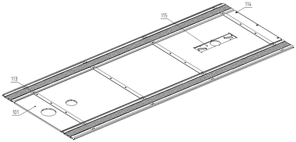
[0028] according to Figures 2 to 4 As shown, the built-in roof structure includes a paper honeycomb roof 101, a roof grille 102, a roof profile 103, a ventilation plate 104, a roof profile 2 105, a roof main beam 106, a handrail installation chute 107, and an air duct clapboard angle iron 108 , Air duct clapboard angle iron 2 109, blocking strip 110, smoke probe and camera integrated module housing 111, air duct bottom plate 112, shock pad 113, glue filling screw 114, smoke...


PUM


Abstract

The invention provides an integrated module structure of an interior roof panel and an air duct of a subway vehicle, including an interior ceiling panel structure, an air duct structure, and a thermal insulation layer. It is used to hoist the interior roof and air duct integrated module to the roof profile on the top of the car body. The air duct structure includes an inverted U-shaped air duct shell, a partition in the air duct shell along the direction of the car body, and sealing rings at both ends. The duct shell and the lower side of the partition are fixedly connected with the built-in top plate structure, and the partition divides the space enclosed by the air duct shell and the built-in top plate into a plurality of air supply cavities. Air supply cavities on both sides are formed on both sides of the air supply structure of the interior roof structure, and the air supply cavity in the middle supplies air to the end of the carriage, and the thermal insulation layer is fixedly connected to the outside of the air duct shell. The interior roof is integrated with the air duct, which eliminates the problem of poor air duct sealing caused by assembly, reduces the assembly process, and reduces the weight of the vehicle body.

Description

technical field [0001] The invention belongs to the technical field of rail vehicle urban rail vehicle interior installation systems, and in particular relates to a subway vehicle interior roof and air duct integrated module structure. Background technique [0002] At present, the existing subway vehicle interior roof and air duct structure is a split structure. Because the split structure needs to consider the structural strength of each component separately, it is difficult to further reduce the weight of the interior roof and air duct, which cannot meet the lightweight of subway vehicle interiors. design needs. In addition, the existing subway vehicle interior roof and air duct structure also has the problem of insufficient assembly accuracy. Due to structural constraints, it is difficult to ensure the theoretical gap between the roof and the air duct, resulting in the gap between the air duct air supply port and the ventilation grille air inlet. The sealing can not meet...

Claims


Application Information

Patent Timeline
Patent Type & Authority Patents(China)
IPC IPC(8): B61D17/14B61D27/00
CPCB61D17/14B61D27/009
Inventor 杜乐尹艺霏聂波苏学威
Owner CRRC CHANGCHUN RAILWAY VEHICLES CO LTD
Why Eureka
Try Eureka