Beam column connection piece, building framework structure and mounting method

A beam-column connection and column technology, which is applied in the direction of building construction, construction, and building material processing, can solve the problems of affecting the connection strength and stiffness of the joint, the shaking of the beam and beam-column connector, and the lack of connection and fixing positions. Achieve the effect of stable and reliable connection nodes, multiple connection and fixing positions, and convenient connection and fixing

Inactive Publication Date: 2013-01-02
何晓虹
View PDF9 Cites 9 Cited by
  • Summary
  • Abstract
  • Description
  • Claims
  • Application Information

AI Technical Summary

Problems solved by technology

In this patent, in order to install the crossbeam as H-shaped steel or I-shaped steel, the end of the crossbeam is processed into a T shape, which increases the process and increases the cost; The two position-limiting protrusions and their corresponding side protrusions form an accommodating groove, and each side wall of the accommodating groove is provided with a fastener fixing threaded hole; the horizontal part of the T-shaped end of the beam ( The upper wing plate) is directly supported on the top surface of the limit protrusion, the vertical part (web) is accommodated in the accommodation groove, and the fastener passes through the fastener to fix the threaded hole and the T-shaped end of the beam. The abutment of the vertical part fixes the beam with the two limiting protrusions, and only the vertical part is connected and fixed with the two limiting protrusions through fasteners. There are few connection and fixing positions, which affect the connection strength and stiffness of the joint; and because the vertical part There is a gap between the beam and the accommodating tank, and the fasteners cannot be used to completely fix the beam and the beam-column connector. There will be a certain gap between the beam and the beam-column connector, so spot welding is necessary after fixing with the fastener fixed

Method used


Image

  • Beam column connection piece, building framework structure and mounting method
  • Beam column connection piece, building framework structure and mounting method
  • Beam column connection piece, building framework structure and mounting method

Examples


Embodiment 1

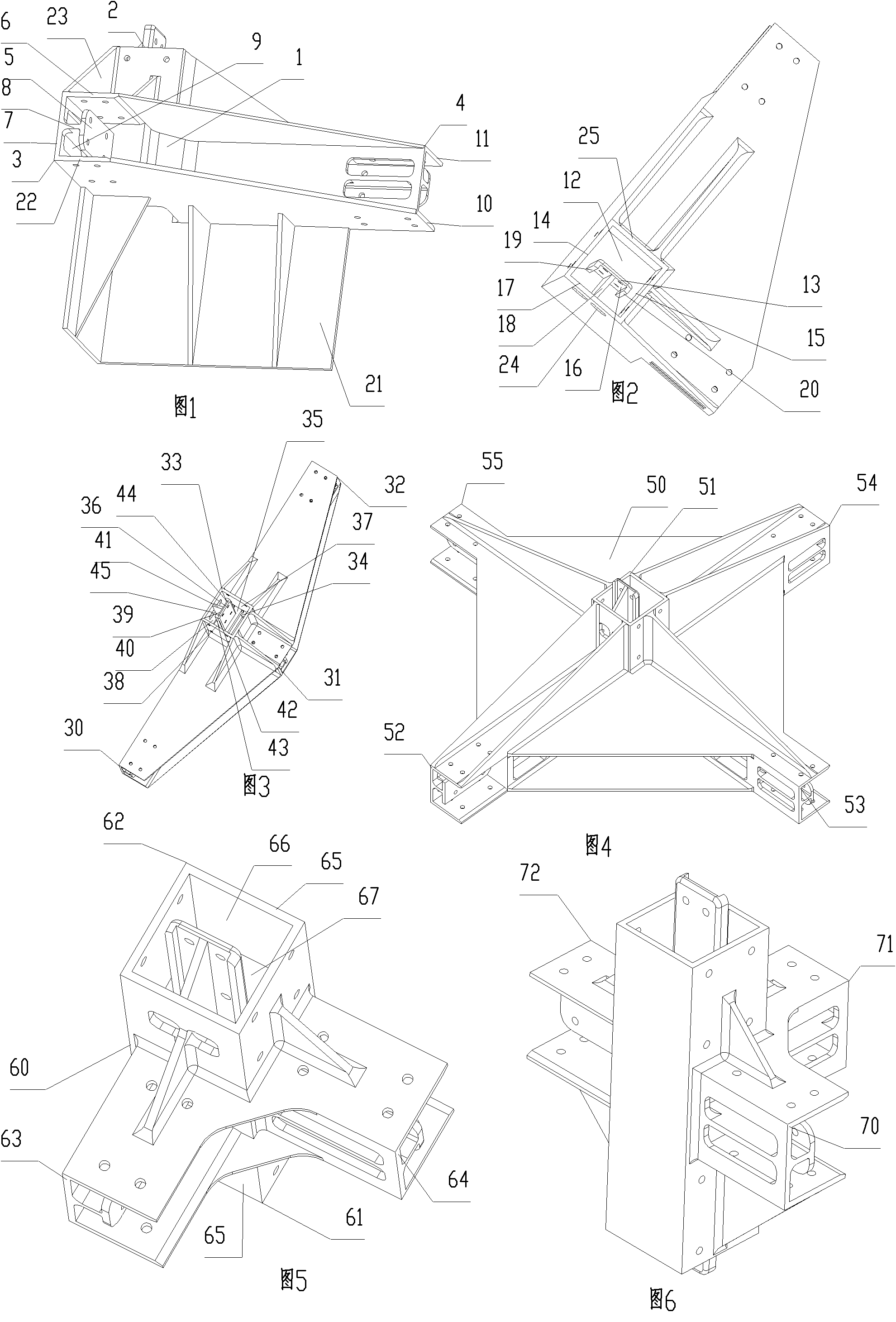
[0064] Such as figure 1 , figure 2 As shown, the beam-column connector is the bottom beam-column connector, including an integrally formed beam-column connector body 1, an upper column plug joint 2 that needs to be plugged and fixed with the end of the H-shaped steel column in the vertical horizontal direction, and two Directly support the H-shaped steel beam parallel to the horizontal plane, and the beam plug joint 3 and the beam plug joint 4 connected and fixed to the end of the beam.

[0065] The beam plug joint 3 retains the first support part 22 that is horizontally protruded from the side of the beam-column connector body 1 and directly supports the lower wing of the beam, placed directly above the first support part 22, and the side of the vertical beam-column connector body 1 is horizontal The first fixing part 5 fixed to the web of the beam is protrudingly provided, and the first fixing part 5 is arranged directly above the first fixing part 5 and horizontally protr...

Embodiment 2

[0070] Such as image 3As shown, different from Embodiment 1, there are three beam plug joints, namely beam plug joint 30, beam plug joint 31, beam plug joint 32, and beam plug joint 30, beam plug joint 31, and beam plug joint 32 are perpendicular to each other. , into a T-shape. Two rows of disconnected resisting ribs 34 that resist the end of the column are horizontally protruded at the corresponding positions on the two inner sides opposite to the accommodation hole 33, and a resisting rib 35 is connected at the middle position of the two inner sides opposite to the accommodation hole 33. . The upper column plug joint includes a vertical resisting rib 35, a third fixed portion 36 fixed to the web of the column, and a reinforcing rib 41 connecting one side 39 of the third fixed portion 36 and one side 40 of the accommodating hole 33. The reinforcing ribs 43 and 44 on the side surface 42 of the third fixing part 36 and near the two ends of the third fixing part 36 . The di...

Embodiment 3

[0072] Such as Figure 4 As shown, the beam-column connector is the bottom beam-column connector, including an integrally formed beam-column connector body 50, an upper column plug joint 51 that needs to be plugged and fixed with the end of the vertical column in the direction of the vertical horizontal plane, four in ten The glyph directly supports the cross beam parallel to the horizontal plane, the beam plug joint 52, the beam plug joint 53, the beam plug joint 54, and the beam plug joint 55 that are fixedly connected with the end of the cross beam. The bottom surface of the beam-to-column connector body 50 is a plane. The structure of the upper column plug joint 51 is the same as that of the upper column plug joint in Embodiment 1, and the structure of the four beam plug joints is the same as that of the beam plug joint in Embodiment 1.


PUM


Abstract

The invention provides a beam column connection piece, a building framework structure and a mounting method. The beam column connection piece comprises a beam column connection piece body, a stand column splicing head, and a beam splicing head, which are integrally formed; the beam splicing head comprises a first supporting part for directly supporting a lower flange of a beam, and a first fixing part which is arranged above the first supporting part, is horizontally and convexly arranged on the lateral face of the beam column connection piece body, and is fixedly connected with a web of the beam; a distance between the first supporting part and the first supporting part in a vertical direction is more than the thickness of the lower flange of the beam; the width of the first fixing part in the vertical direction is less than a distance between the two opposite faces of the two flanges of the beam; and the beam column connection piece is further provided with a stopping part of the end part of a stand column. The beam column connection piece has the advantages in that the end part of an H-shaped or transverse H-shaped beam has no need of being machined and has more connection and fixation positions; the connection nodes are stable and reliable; the strength and the rigidity of the connection position are good; and the building framework structure has the advantages of convenience in installation, less process and low labor intensity.

Description

technical field [0001] The invention relates to a beam-column connector, a building frame structure and an installation method of houses, pavilions, booths, bridges and other buildings, in particular to a beam-column connector, a frame structure and an installation method of a building frame steel structure. Background technique [0002] In the invention patent with application number 201110114982.3, a beam-column connector and its forming method, building frame structure and installation method are disclosed. The beam-column connector includes an integrally formed beam-column connector body, a column plug connector, and a horizontal support connector. Although this patent has greatly reduced fastening connections such as bolts or welding connection links, it has greatly reduced the defects of excessive stress concentration on the connection position between beams and columns or between beams and beams, which makes the connection position poor in stress and weak in connectio...

Claims


Application Information

Patent Timeline
Patent Type & Authority Applications(China)
IPC IPC(8): E04B1/58E04B1/19E04G21/14
CPCE04B2001/2454E04B1/58E04B2001/2448E04B1/19E04B2001/249E04B2001/2406E04G21/14E04B2001/2463E04B1/24
Inventor 何晓虹
Owner 何晓虹
Why Eureka
Try Eureka